110 | © Danfoss | August 2018 AQ00000211
11.9 OPEN LOOP JOYSTICK – VEHICLE SPEED DEPENDENT FLOW SCALING
As a risk mitigation method, when using the open loop joystick functionality in AUX steering mode, the PVED-CLS’s
AUX control algorithm can also limit and scale the maximum allowed output flow in proportion to the vehicle speed (i.e.
the faster the vehicle goes the lower the maximum allowed flow will be).
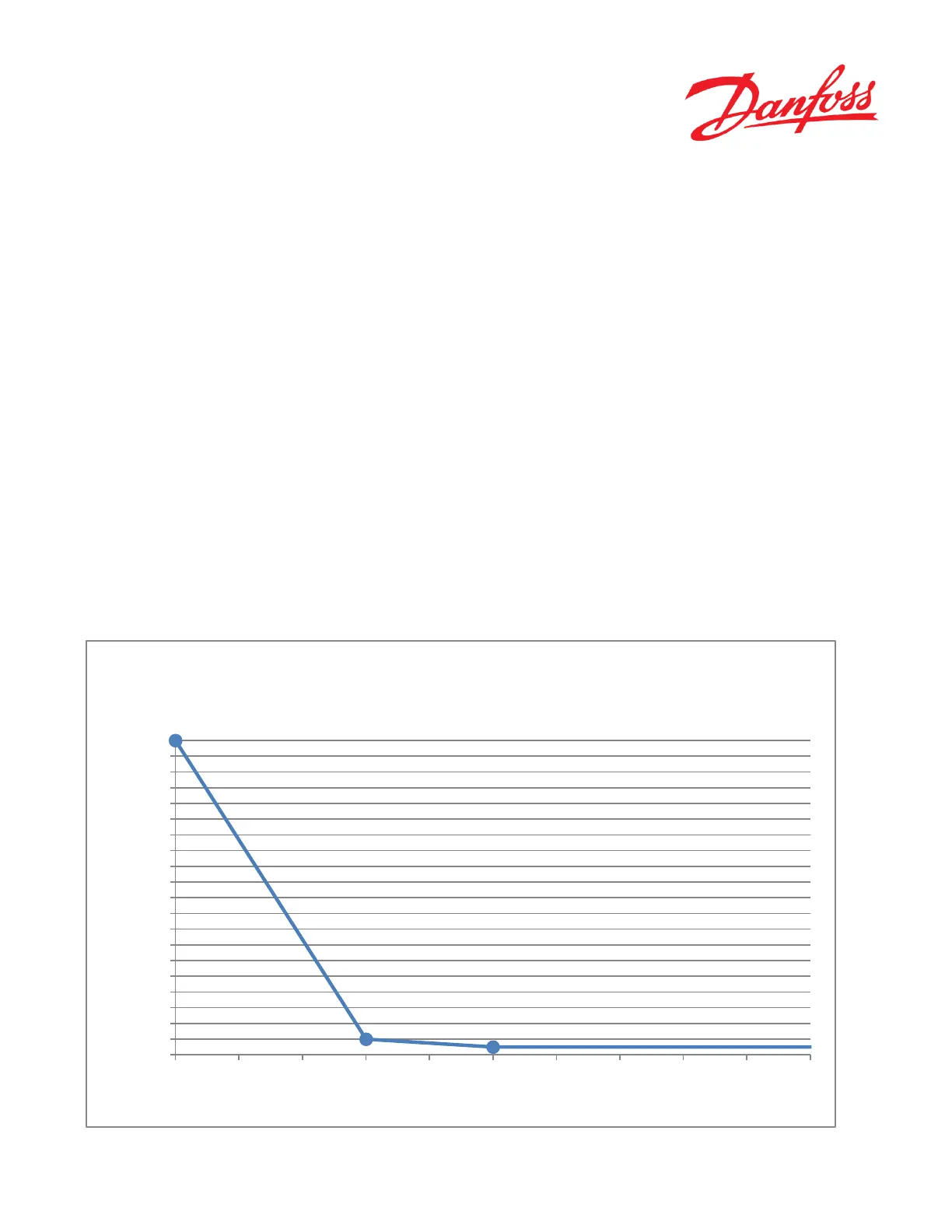
The flow scaling algorithm calculates the maximum flow allowed based on vehicle speed. The determined maximum flow
is scaled to the full joystick input range so that always the full joystick stroke is utilized. This gives better controllability
at high vehicle speeds as the joystick sensitivity is reduced. A calculation example of the flow scaling function is shown
below:
If the flow limit at a given vehicle speed is calculated to 400 IR and the joystick position is 700 IR, the resulting flow
command calculated by PVED-CLS will be 700 IR * (400IR/1000IR) = 280IR.
The flow scaling function is configured by following parameters: P3696 and P3697 set the vehicle speed (range from 0 to
100 km/h ) and P3690, P3692 and P3694 set the maximum flow (range from 0 to 1000 IR).
These parameters represent the three points on the curve below (Point M, N and O). The Open Loop AUX Joystick
algorithm will make linear interpolation in between each of the three points. It is allowed to move the three points in any
direction, limited by the following rules:
• Point M is always specified at Vehicle speed limited flow = 0 km/h
• Point O “Max flow” is valid for Point O “Vehicle speed limited flow” and vehicle speeds above Point O “Vehicle
speed limited flow”
• Point M “Max flow” ≥ Point N “Max flow” ≥ Point O “Max flow”
• Point O “Vehicle speed limited flow” > Point N “Vehicle speed limited flow” > Point M “Vehicle speed limited
flow”
Figure 57
Point M
Point N
Point O
0
50
100
150
200
250
300
350
400
450
500
550
600
650
700
750
800
850
900
950
1000
0 5 10 15 20 25 30 35 40 45 50
Max flow [IR]
Vehicle speed [km/h ]
AUX - open loop joystick vehicle speed dependent
flow scaling
 Loading...


