88 | © Danfoss | August 2018 AQ00000211
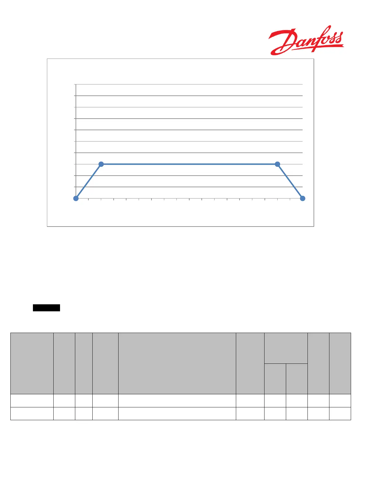
Figure 42
The range is from 1° to 160° for P3568, in steps of 1°. For P3569 the range goes from 0% to 100% in steps of 1%.
The values recommended by Danfoss are P3568 set to 20 and P3569 set to 15 i.e. anti-drift will be enabled all the time
and 15% of the full flow will be added or deducted, depending on direction, to the calculated ideal ccm per revolution-
output, when the difference between the measured steering wheel position and the actual position of the wheels is 20° -
160° (due to Point B and Point C’s coordinates). When steering wheel angle difference is > 160°, linear interpolation,
between Point C and the fixed point D, will determine the anti-drift correction volume. Furthermore, anti-drift function
will also improve consistency in lock-to-lock on steering wheel.
Important
If anti-drift is not required, the function can be disabled by setting P3569 to 0.
Name
Description of parameter
Range
Safety critical
parameters ‘S’
steering wheel drift
P3568 U8 Deg
The difference between the observed and ideal STW steering angle at
which and above which the max. EFU correction ("STW Anti-drift - Max
flow correction") shall be applied.
OEM 1 160 20
flow correction in
P3569 U8 % Max flow correction which can be requested by the EFU algorithm OEM 0 100 15
Table 38
Point A
Point B
Point C
Point D
0
5
10
15
20
25
30
35
40
45
50
0 10 20 30 40 50 60 70 80 90 100 110 120 130 140 150 160 170 180
Anti-
drift correction [% of max flow]
|Steering wheel angle difference [degrees]|
STW - Anti-drift (EFU)
 Loading...


