FC 300 Design Guide
How to Install
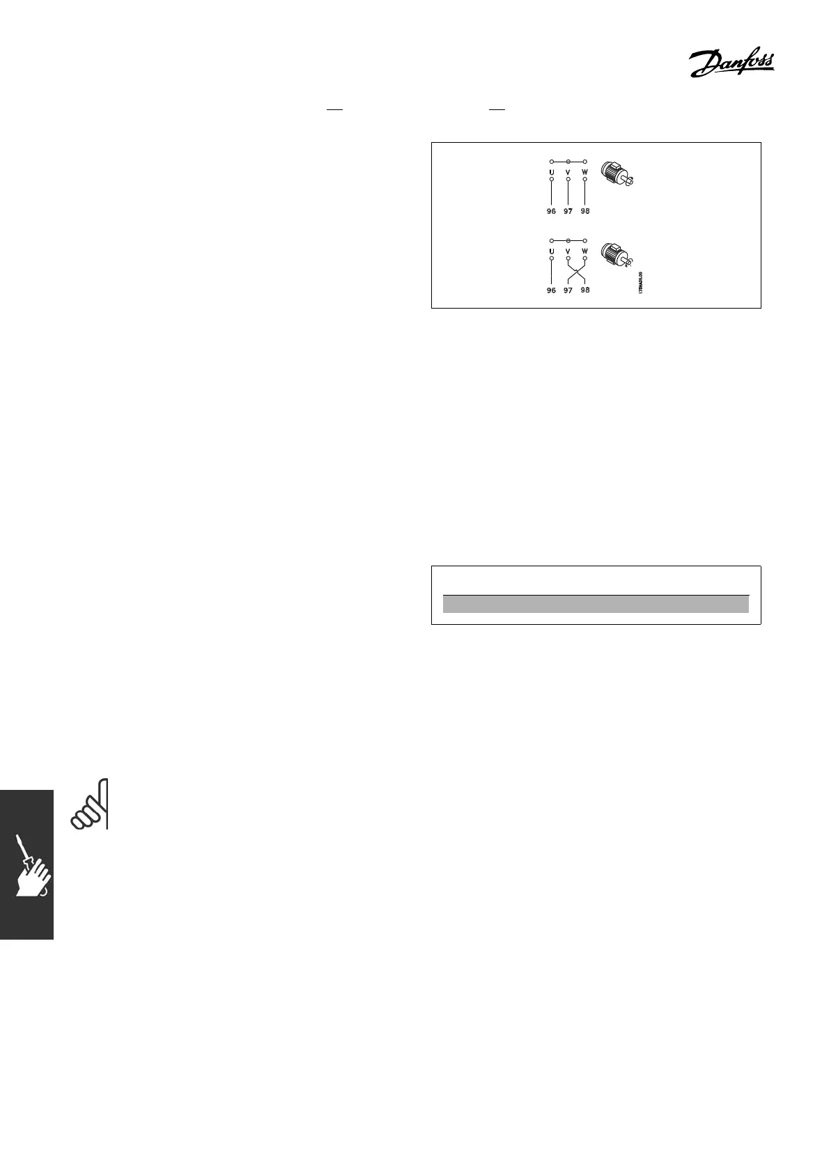
" Direction of Motor Rotation
The default setting i s clockwise rotation
with the adjustable frequency drive output
connected as follows.
Terminal 96 connected to U-phase
Terminal 97 connected to V-phase
Terminal 98 connected to W-phase
The d irection of motor rotation is changed by
switching two phases in the motor cable.
" Thermal motor protection
The electronic thermal relay in FC 300 has received the UL-approval for single moto r protection,
when parameter 1-26 Motor thermal protection is set for ETR Trip and parameter 1-23 Motor
current, I
M, N
is set to the rated motor current (see motor nameplate).
" Installation of Brake Cable
(Only for adjustable frequency drives ordered with brake chopper option).
The connection cable to the brake resistor must be shie lde d.
1. Connect the shield by means of cable
clampstotheconductivebackplateonthe
adjustable frequency drive and to the m etal
cabinet of the brake resistor.
2. Size the brake cable cross-section to
match the brake torque.
No. Function
81, 82 Brake resistor terminals
See Brake instructions, MI.90 .FX.YY and MI.50.SX.YY for more information about safe installation.
NOTE
Voltages up to 960 V DC, depending on the supply voltage, may occur on the terminals.
104
MG.33.B3.22 - VLT is a registered Danfoss trademark
 Loading...


