FC 300 Design Guide
Introduction to FC 300
The Remote reference is calculated once every scan interval and initially consists of two p arts:
1. X (the ext ernal reference) : A sum of up to four externally selected references, com prising any
combination (de term ined by the setting of par. 3-15, 3-16 and 3-17) of a fixed preset reference (par.
3-10), variable analog references, variable digital pulse references, and various seria l bus references
in whatever unit the adjustable frequency drive is controlled ([Hz], [RPM], [Nm] etc.) .
2. Y- (the relative reference): A sum of one fixed preset reference (par. 3-14) and
one variable analog referenc e (par. 3-1 8) in [%].
The two parts are combined in the following calculation: Auto reference = X + X * Y / 100%. The
Catch up / slow-down function and the Freeze reference function can both be activated by digital
inputs on the adjustable frequency drive. They are described in par. group 5-1*.
The scaling of analog references is described in par. groups 6-1* and 6-2*, and the scaling
of digital pulse re ferences is described in par. group 5-5*.
Reference lim it s and ranges are set in par. g roup 3-0*.
References and feedback can b e scaled in physical units (i.e. RPM, Hz, °C) or simply in % rela tin
g
to the values of par. 3-02 Minimum Referen ce and par. 3-03 Maximum Reference.
In this case, all analog and pulse inputs are scaled according to the following rules:
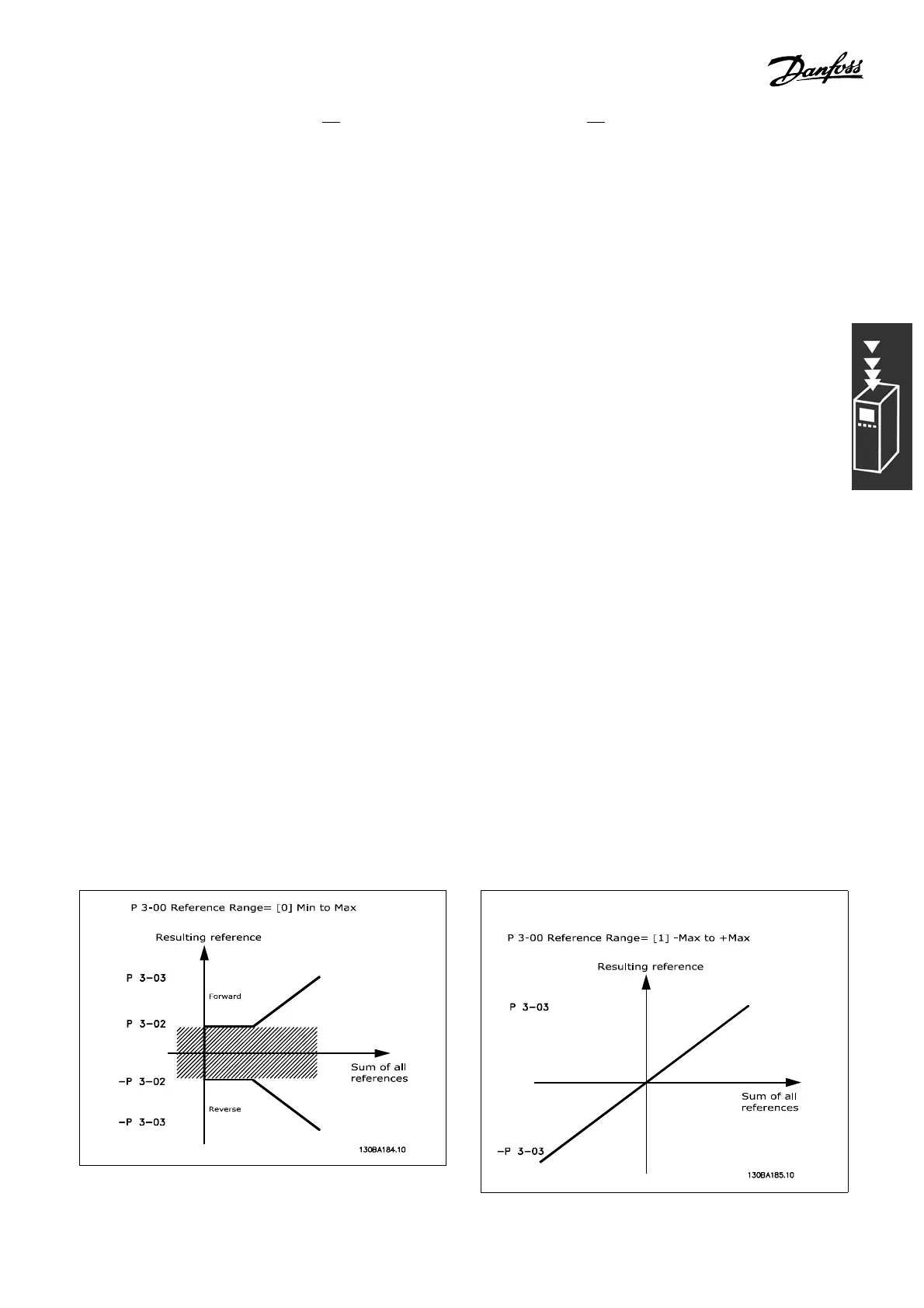
• When par. 3-00 Reference Range is [0] Min - Max, 0% reference equals 0 [unit], where unit
can be any unit e.g. rpm, m/s, bar etc., 100% re ference equals the Max (abs (par. 3-03
Maximum Reference), abs (par. 3-02 Minimu m Ref erence )).
• When par. 3-00 Re ference Range: [1] -Max - +Ma x, 0% reference equals 0 [unit], -100%
reference equals -Max Reference, 100% reference equals Max Reference.
Bus references are sc aled according to the foll owing rules:
• When par. 3-00 Reference Range is [0] Min - Max. To o btain m ax resol
ution on the bus reference, the
scaling on the bus is: 0% reference eq uals Min Reference, 100 % reference equals Max re ference.
• When par. 3-00 Reference Range: [1] -M ax - +Max, -100% reference eq uals -Max
Reference, 100% reference equals Max Reference.
Par. 3-00 Reference Range,3-02Minimum Reference and 3-03 Maximum Reference togethe r define the
allowed range of the sum of all references. The sum of all references is clampe d when necessary. The relation
between the resulting reference (after clampin
g) and the sum of all references is shown below.
25
MG.33.B3.22 - VLT is a registered Danfoss trademark
 Loading...


