FC 300 Design Guide
How to Install
" Electrical Installation, Control Terminals
1. Mount terminals from the accessory bag
to the front of the FC 300.
2. Connect terminals 18, 27, and 37 to +24 V
(terminal 12/13) with the control cable.
Default settings:
18 = start
27 = coast inverse
37 = safe stop inverse
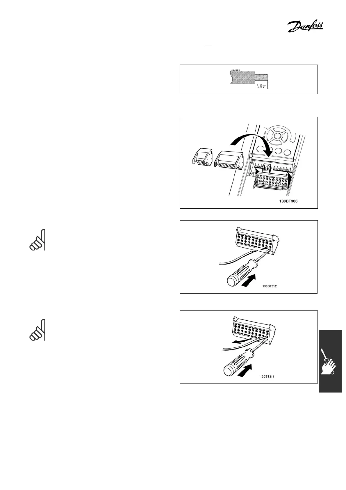
NOTE
To mount the cable to the terminal:
1. Strip isolation of 0.35 - 0.4 in. (9-10 mm)
2. Insert a screwdriver in the square hole .
3. Insert the cable in the adjacent circular hole.
4. Remove the screwdriver. The cable is now
mounted to the terminal.
NOTE
To remove the cable from the te rm inal:
1. Insert a screwdriver in the square hole .
2. Pull out the cable.
93
MG.33.B3.22 - VLT is a registered Danfoss trademark
 Loading...


