FC 300 Design Guide
How to Program
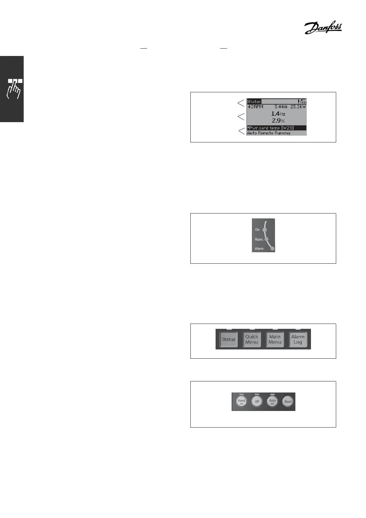
" Control Panel - D isplay
The LCD display has back lighting and a total of 6 alpha-numeric lines. The display lines show the direction of
rotation (arrow), the chosen Set-up as well as the programming Set-up. The display is d ivided into 3 sections:
Top section shows up to 2 measurements
in normal operating status.
ThetoplineintheMiddle section shows up to
5 measurements with related unit, regardless of
status (except in the c ase of alarm/warning).
Bottom section always shows the state of the
adjustable frequency drive in Status mode.
130BP074.10
Top section
Middle section
Bottom section
The Active Set-up (selected as the Active Set-up in par. 0-10) is shown. When programming a Set-up
other than the Active Set-up, the number of theprogrammedSet-upappearstotheright.
" Control Panel - LEDs
In the lower le ft corner of the control panel, three
LEDs are located: A red alarm LED, a yellow
warning LED, and a green voltage LED.
130BP040.10
If certain threshold values ar e exceeded, the alarm and/or warning LED light(s) up. A
status a nd alarm text appe
ar o n the control panel.
The voltage LED is activated when the adjustabl e frequency drive receives voltage or 24 V
external supply. At the same time, the back light is on.
" Control Panel - Contro
lKeys
The control keys are divided into functions. The
keys below the display and indicator lamps are
used for parameter Se
t-up, including choice of
display indication during normal op eration.
130BP045.10
Keys for local control are found at the bottom
of the control panel.
130BP046.10
122
MG.33.B3.22 - VLT is a registered Danfoss trademark
 Loading...


