FC 300 Design Guide
How to Program
Function:
This parameter is only active in adjustable freq u ency
drives with an integral dynamic brake.
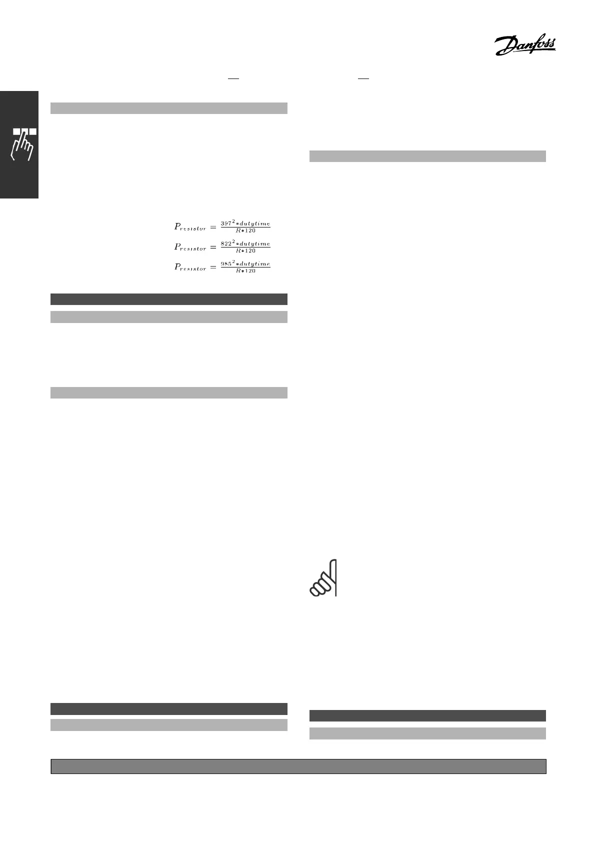
The monitoring limit is a p roduct of the maximum
duty cycle (120 sec.) and the maximum
power of the brake resistor at that duty cycle.
See the formula below.
For 200 - 240 V units:
For 380 - 500 V units
For 575 - 600 V units
2-13 Brake Power Monitoring
Option:
*
Off [0]
Warning [1]
Trip [2]
Warning a nd Trip [3]
Function:
This parameter i
s only active in adjustable freq uency
drives with an integral dynamic brake.
Allows monitoring of the power to the brake
resistor. The power is calculated on the basis of
the resist
or ohm value (par. 2-11), the DC link
voltage, and the resistor duty time. If the power
transmitted over 120 s exceeds 100% of the
monito
ring limit (par. 2-12) and Warning [1] is
selected, a warning appears on the display.
The warning disappears if the power goes below
80%.
If the calculated power exceeds 100% of
the monitoring limit and Trip [2] is selected in par.
2-13 Power Monitoring, the adjusta ble frequency
dr
ive trips and displays an alarm.
If power monitoring is set to Off [0] or Warning
[1], the brake function rema ins active, even if the
m
onitoring limit is exceeded. This may lead to
thermal overload of the resistor. It is also possible
to have a warning via a relay/digital outputs.
The mea suring accuracy of the power monitoring
depends on the accuracy of the resistance of
the resistor (better than ± 20% ).
2-15 Brake Check
Option:
*
Off [0]
Warning [1]
Trip [2]
Trip and Stop [3]
Function:
This parameter is only active in adjustable frequency
drives w ith an integral dynamic brake.
Enables the integration of a test and m onitor
function, which displays a warning or an alarm. On
power-up, the functions is tested for disconnection
of the brake resistor. The test is carried out during
braking. Testing for disconnection of the IGBT,
however, is carried out when there is no braking.
A warning or trip disconnects the brake function.
The testing sequence is as follows:
1. The DC link ripple amplitude is measured
for 300 ms without braking.
2. The DC link r ipple am plitude is measured for
300 ms with the brake turned on.
3. If the DC link ripple amplitude while braking
is lower tha n the DC link ripple amplitude
before braking + 1 %. Brake check failed,
return a warning or ala rm.
4. If the DC link ripple amplitude while braking
is higher than the DC link ripple amplitude
before braking + 1 %. B rake check OK
Select Off [0]. This function still m onitors whether
the brake resistor and the brake IGBT short circuit
during operation. If so, a warning appears. Sel
ect
Warning [1] to monitor the brake resistor and brake
IGBT for to short circuiting. During power-up,
disconnection of the brake resistor is chec
ked.
NOTE
Remove a warning arisen in connection
with Off [0] or Warning [1] by cycling
the mains supply. The fault must be
corrected first. Wit h Off [0] or Warning [1 ], the
adjustable frequency drive keeps running even
if a fault is located. In the ca
se of Trip [2], the
adjustable frequency drive cuts out while displaying
an alarm (trip locked). This happens if the brake
resistor is short circuite
d, is disconnected, or if
the brake IGBT is short circuited.
2-17 Over-voltage Control
Option:
*
Disabled [0]
*
default setting ()display text []value for use in communication via serial communication port
152
MG.33.B
3.22 - VLT is a registered Danfoss trademark
 Loading...


