NOTICE
The maximum current for the analog outputs 0–10 V is 1 mA.
NOTICE
Where live zero monitoring is used, it is important that any analog inputs not being used for the frequency converter,
that is, being used as part of the building management system decentral I/O, should have their live zero-function
disabled.
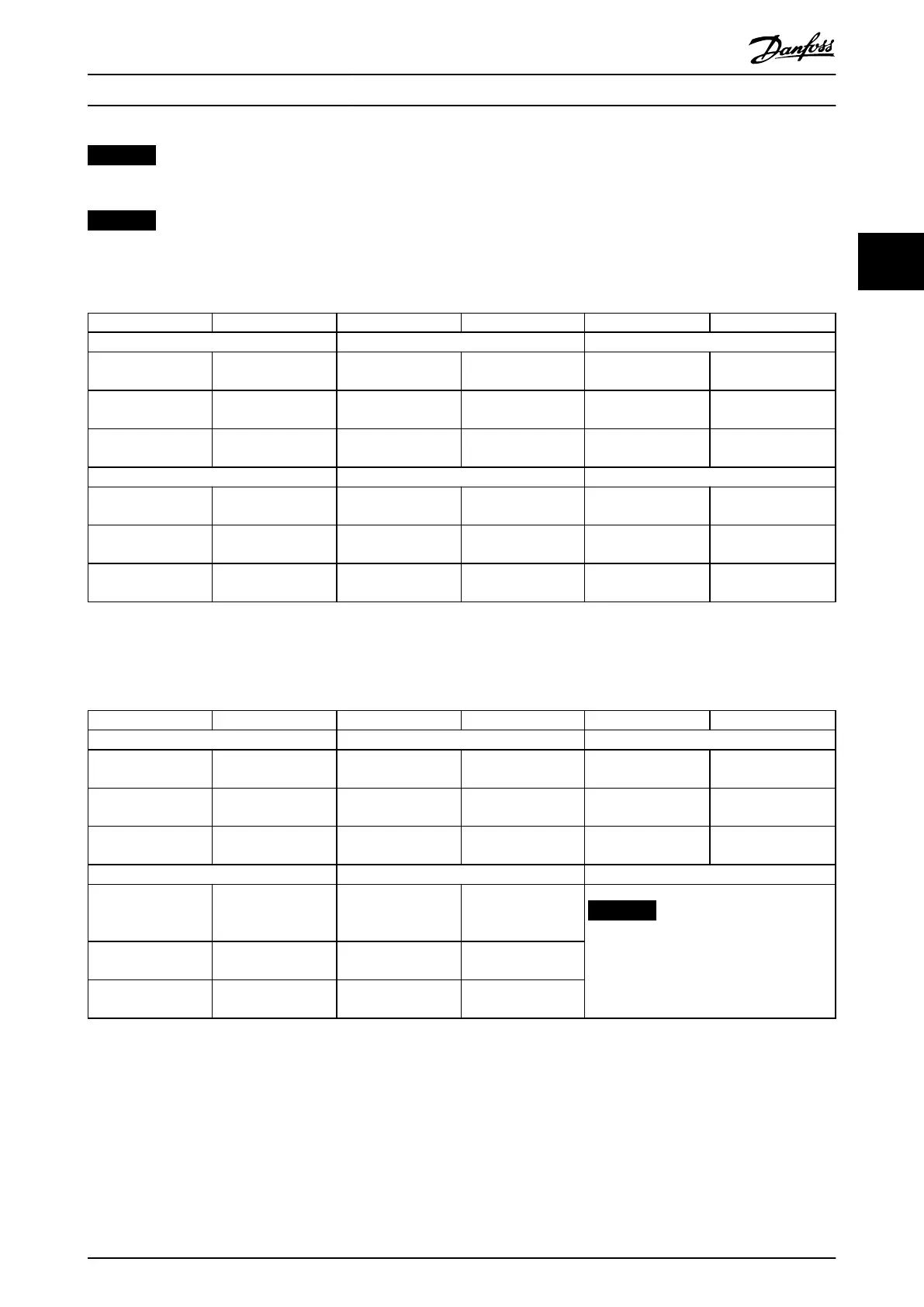
Terminal Parameters Terminal Parameters Terminal Parameters
Analog inputs Analog inputs Relays
X42/1 Parameter 26-00 Termi
nal X42/1 Mode, 26-1*
53 6-1* Relay 1 Term 1, 2, 3 5-4*
X42/3 Parameter 26-01 Termi
nal X42/3 Mode, 26-2*
54 6-2* Relay 2 Term 4, 5, 6 5-4*
X42/5 Parameter 26-02 Termi
nal X42/5 Mode, 26-3*
Analog outputs Analog output
X42/7 parameter group 26-4*
Analog Out X42/7
42 6-5*
X42/9 parameter group 26-5*
Analog Out X42/9
X42/11 parameter group 26-6*
Analog Out X42/11
Table 3.31 Relevant Parameters
It is also possible to read the analog inputs, write to the analog outputs, and control the relays, using communication via
the serial bus. In this instance, these are the relevant parameters.
Terminal Parameters Terminal Parameters Terminal Parameters
Analog inputs (read) Analog inputs (read) Relays
X42/1 Parameter 18-30 Anal
og Input X42/1
53 Parameter 16-62 Anal
og Input 53
Relay 1 Term 1, 2, 3 Parameter 16-71 Relay
Output [bin]
X42/3 Parameter 18-31 Anal
og Input X42/3
54 Parameter 16-64 Anal
og Input 54
Relay 2 Term 4, 5, 6 Parameter 16-71 Relay
Output [bin]
X42/5 Parameter 18-32 Anal
og Input X42/5
Analog outputs (write) Analog output (write)
X42/7 Parameter 18-33 Anal
og Out X42/7 [V]
42 Parameter 6-53 Termin
al 42 Output Bus
Control
NOTICE
Enable the relay outputs via control
word bit 11 (relay 1) and bit 12 (relay
2).
X42/9 Parameter 18-34 Anal
og Out X42/9 [V]
X42/11 Parameter 18-35 Anal
og Out X42/11 [V]
Table 3.32 Relevant Parameters
Setting of on-board real-time clock
The analog I/O option incorporates a real-time clock with battery back-up. This can be used as back-up of the clock function
included in the frequency converter as standard. See chapter 3.2.11 0-7* Clock Settings.
The analog I/O option can be used for the control of devices such as actuators or valves, using the extended closed loop
facility, thus removing control from the building management system. See chapter 3.19 Parameters: 21-** Main Menu -
Extended Closed Loop. There are 3 independent closed-loop PID controllers.
Parameter Descriptions Programming Guide
M0010001 Danfoss A/S © 10/2019 All rights reserved. 249
3 3
 Loading...


