Figure 108. External view of server sled A in a EX3000D dual node chassis with two sleds
For the EX3000S single-node system, a dummy sled is installed over the bottom sled A compartment and there are air flow
covers over the two empty power supply slots.
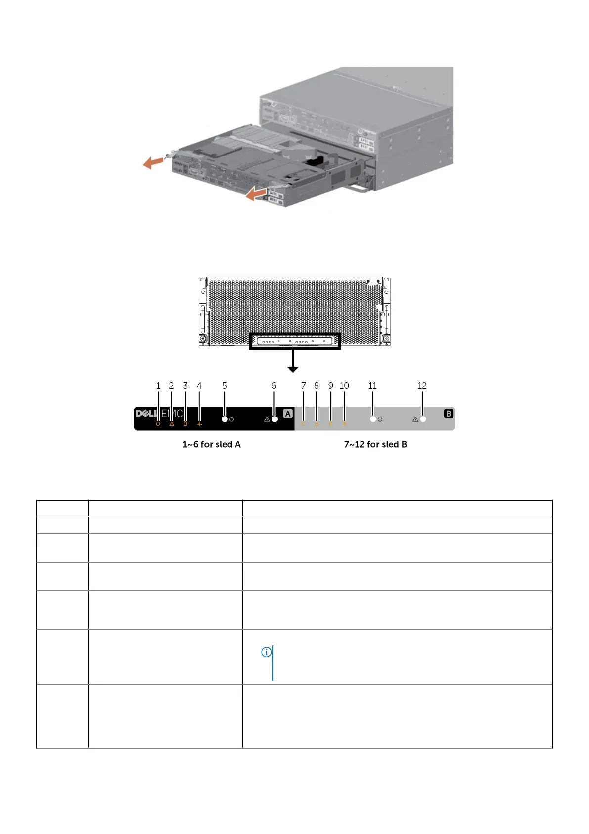
Figure 109. Front-panel features and indicators
Table 49. Server indicators, buttons, or connectors
Item Indicator, Button, or Connector Description
1 Power indicator The power indicator glows when the system is turned on.
2 ID indicator When a system identification button is pressed, the ID indicator blinks blue
to help locate a particular system within a rack.
3 Sled A HDD fault status indicator. The indicator blinks amber if an HDD
experiences an issue.
4 System board status indicator If the system is on, and in good health, the indicator glows solid blue. The
indicator blinks amber if the system is in standby, and if any issue exists
(for example, a failed fan or HDD).
5 Power button
● The power button controls the PSU output to the system.
●
NOTE: On ACPI-compliant operating systems (OSs), turning off
the system using the power button causes the system to perform a
graceful shutdown before power to the system is turned off.
6 System identification button
● The identification button can be used to locate a particular system
within a rack.
● Press to toggle the system ID on and off.
● If the system stops responding during POST, press and hold the system
ID button for more than five seconds to enter BIOS progress mode.
130 EX3000 Platform
 Loading...


