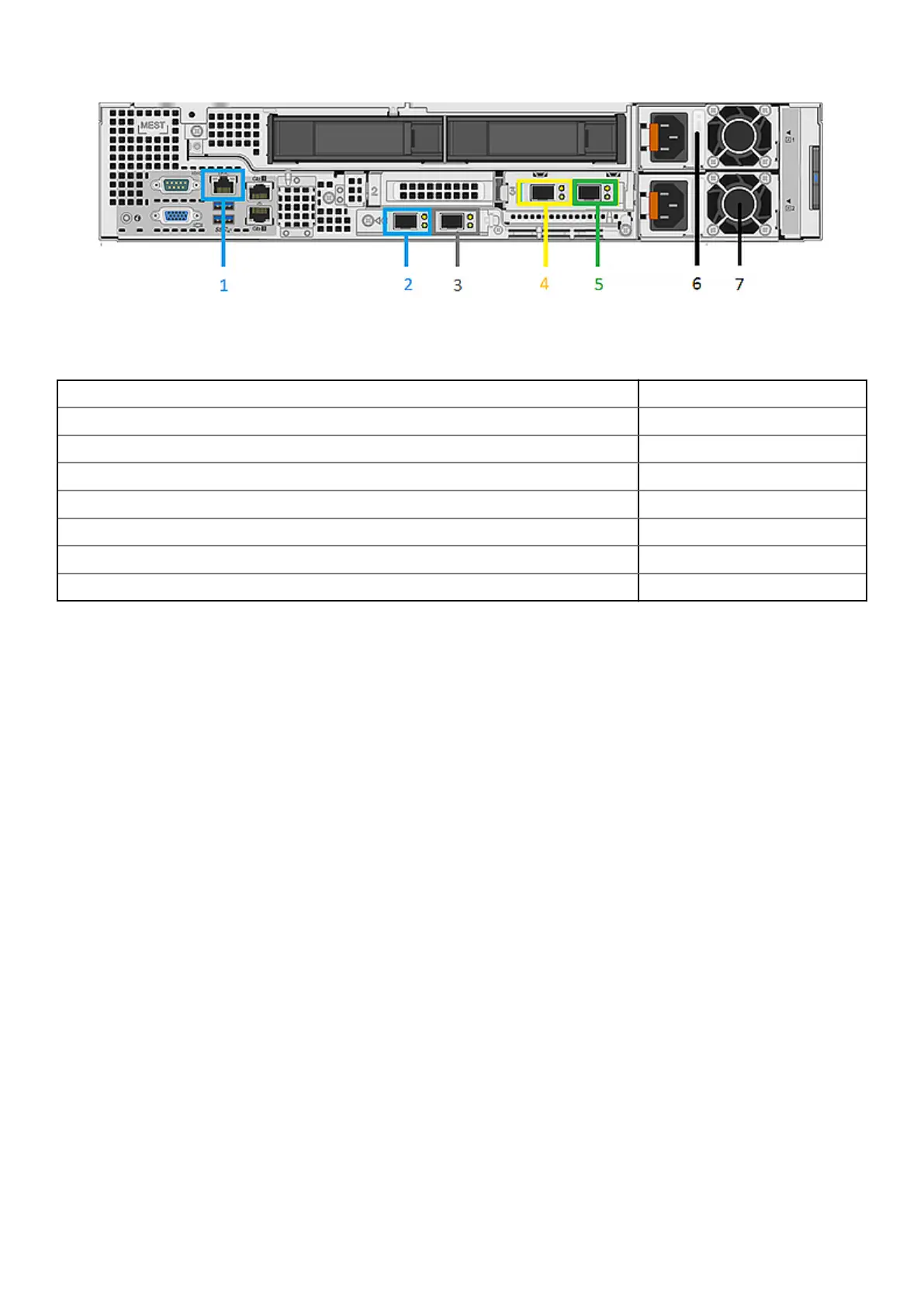
Figure 50. EX500 server chassis back view
In the table below, x is the server number.
Network Cable Description Labeling
1 - iDRAC management port, back-end switch 1 Server x iDRAC *
2 - Back-end switch 1 Server x BE 1 *
3 - Back-end switch 2 Server x BE 2 *
4 - Front-end switch 2 Server x FE 2 *
5 - Front-end switch 1 Server x FE 1 *
6 - Power cable (black) AC PS1
7 - Power cable (grey) AC PS2
EX500 disk drives
Learn about the disk drives that are integrated into the server chassis of the EX500 appliance.
EX500 nodes contain 24 3.5 inch SATA front-accessible, hot-swappable drives in disk bay 1, slots 0-11 and disk bay 2, slots
12-23. Disk size can be 8 TB, 12 TB, or 16 TB. All drives within a node must be of the same drive size, but there can be nodes
of differing drive sizes and quantities (12 or 24) within a rack. In PCIe slot 2 of each node there is a 480 GB Boot Optimized
Storage Subsystem (BOSS) controller card with one M.2 stick.
72
EX500 Platform
 Loading...


