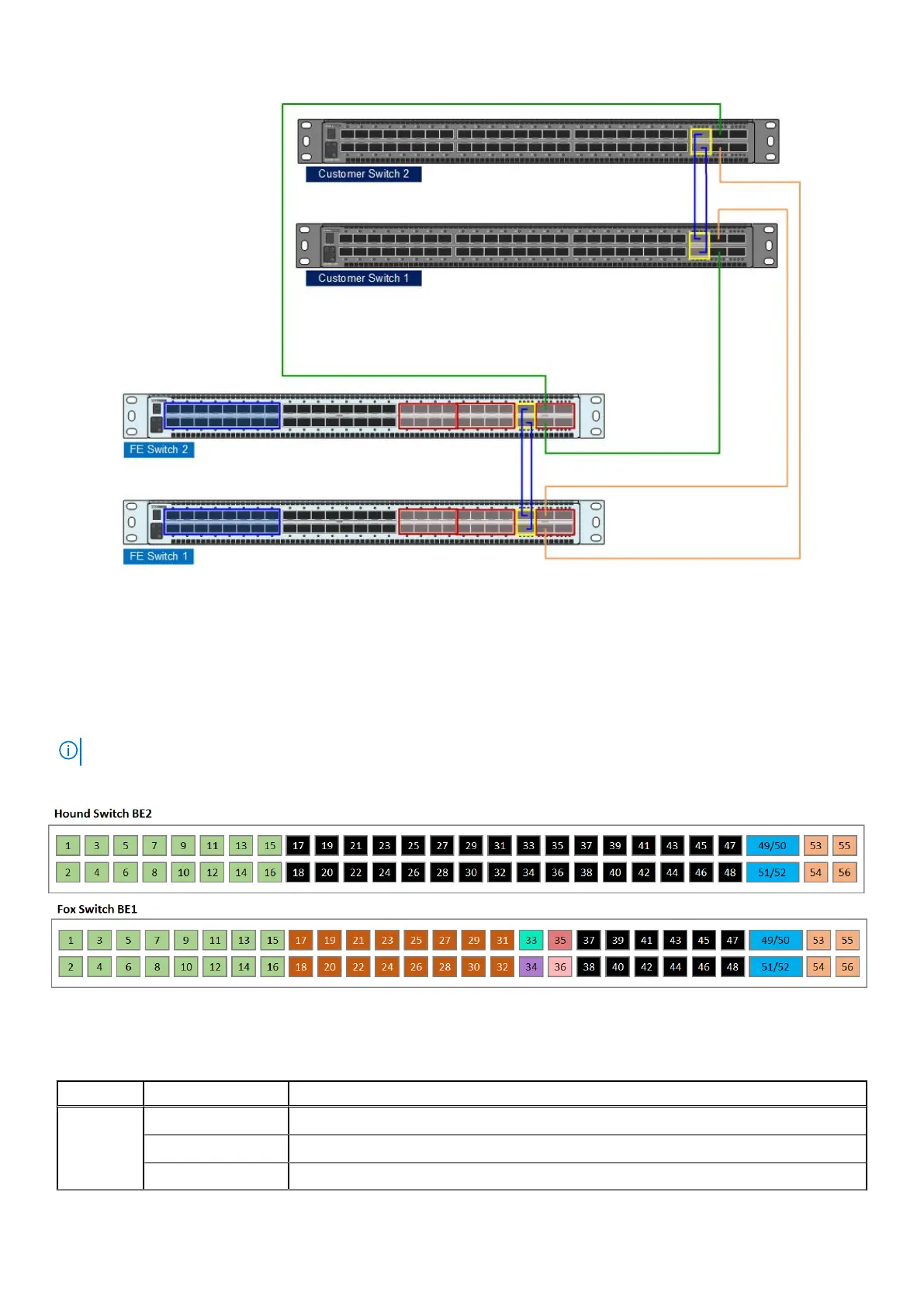
Figure 11. Front-end switch connections to customer switches (4X100 example)
Back-end switch pair
Dell EMC provides two 25 GbE S5248F back-end switches (BE1 and BE2) with two 200GbE (QSFP28-DD) VLT cables. These
switches are referred to as the Hound (BE2) and Fox (BE1) switches.
In the following diagram, all labeled ports relate to an ECS virtual data center (VDC) in which all racks or nodes are EXF900.
NOTE: EXF900 cannot be combined with the other EX Series hardware (EX300, EX300, or EX500) in the same VDC.
All iDRAC cables from nodes and all front-end switch management cable connections route to the Fox (BE1) switch.
Figure 12. Back-end switches
Table 6. Switch port number
Switch Port number Description
Hound 1-16 Private network ports connected to nodes (10/25 GbE)
17-48 Not designated.
49-52 VLT ports (100 GbE)
20 Switches
 Loading...


