Figure 46. EX500 server chassis front view
LED indicators are on the left and right side of the server front panels.
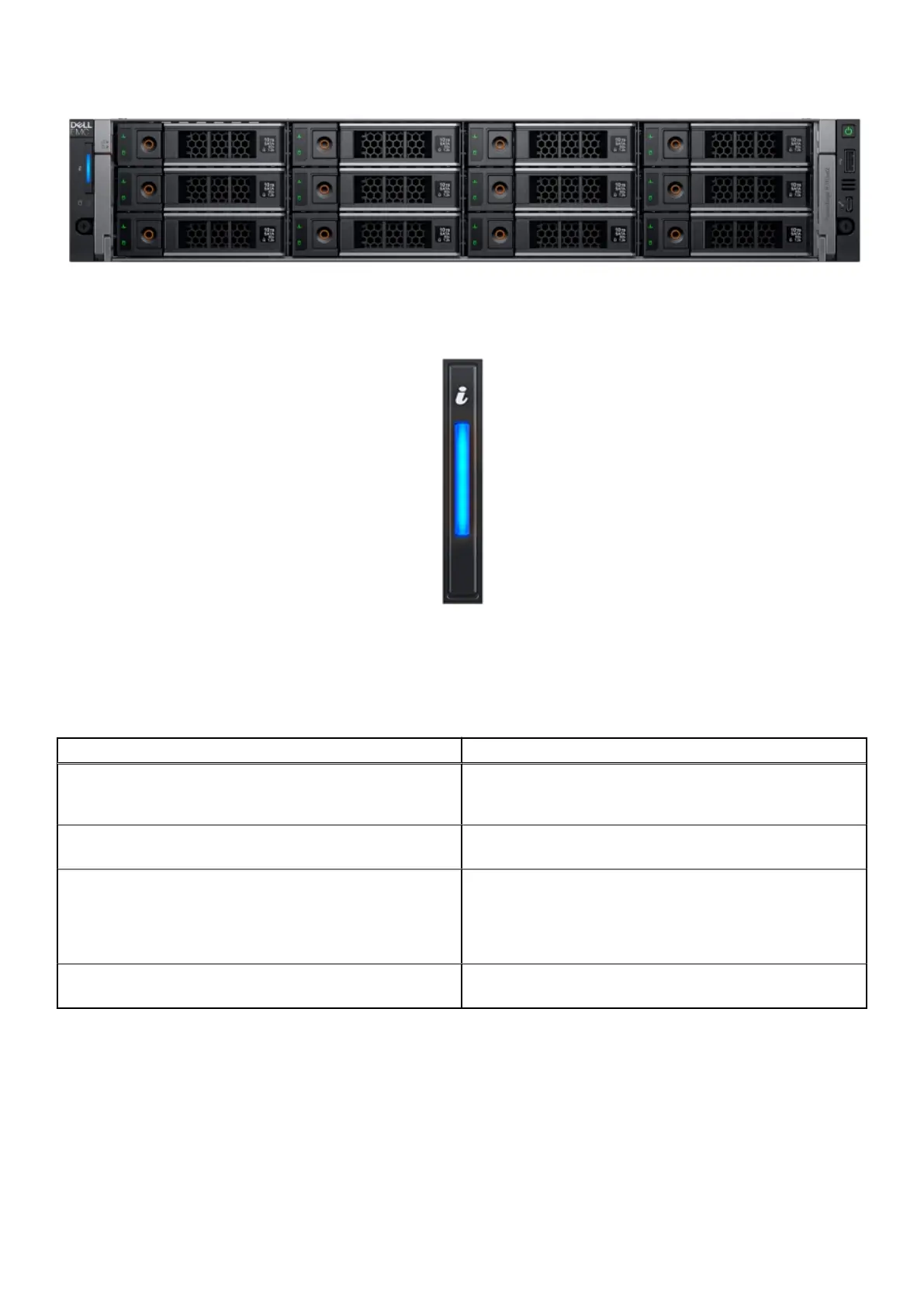
Figure 47. Left control panel
The left control panel LED behavior is broken into two subsets, the light bar and the status LEDs. The light bar also functions as
a button. The light bar indicates chassis health and also functions as System ID when pressed.
Table 31. Decoding of LEDs in light bar
Status ID button
Indicates that the system is turned on, system is healthy, and
system ID mode is not active. Press the system health and
system ID button to switch to system ID mode.
Solid Blue
Indicates that the system is in fail-safe mode. If the problem
persists, see the Getting help section.
Solid Amber
Indicates that the system is experiencing a fault. Check
the System Event Log for specific error messages. For
information about the event and error messages generated
by the system firmware and agents that monitor system
components, see the Error Code Lookup page at qrl.dell.com
Blink Amber
Indicates that the system ID mode is active. Press the system
health and system ID button to switch to system health mode.
Blink Blue
There are two status LEDs to indicate and identify any failed hardware components.
70
EX500 Platform
 Loading...


