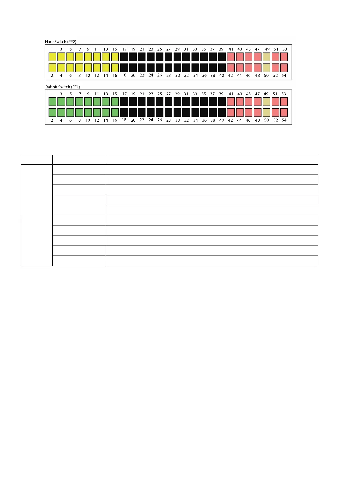
Figure 2. Front-end switches
Table 3. Switch port numbers
Switch Port number Description
Hare 1-16 Data network ports connected to nodes (10/25 GbE)
17-40 Not designated
41-48 Customer uplink ports (10/25 GbE)
49-50 VLT ports (100 GbE)
51-54 Customer uplink ports (100 GbE)
Rabbit 1-16 Data network ports connected to nodes (10/25 GbE)
17-40 Not designated
41-48 Customer uplink ports (10/25 GbE)
49-50 VLT ports (100 GbE)
51-54 Customer uplink ports (100 GbE)
Back-end switch pair
Dell EMC provides two 25 GbE S5148F back-end switches (BE1 and BE2) with two 100 GbE VLT cables. These switches are
referred to as the Hound (BE2) and Fox (BE1) switches.
In the following diagram, all labeled ports relate to an ECS virtual data center (VDC) in which all racks/nodes are EX-Series
(Gen3 hardware), with the exception of ports 39 and 40. Ports 39 and 40 are only used in the scenario where there is Gen2
hardware series integration with EX-Series hardware in the VDC. When Gen2 hardware is mixed with EX-Series hardware, ports
39 and 40 are the only ports used for connectivity.
All iDRAC cables from nodes and all front-end switch management cable connections route to the Fox (BE1) switch.
14
Switches
 Loading...


