NOTE: The connections to the Fox switch are incorrect. The iDRAC connection to the Fox switch should connect to ports
17-32, NIC Port 1 should connect to ports 1-16.
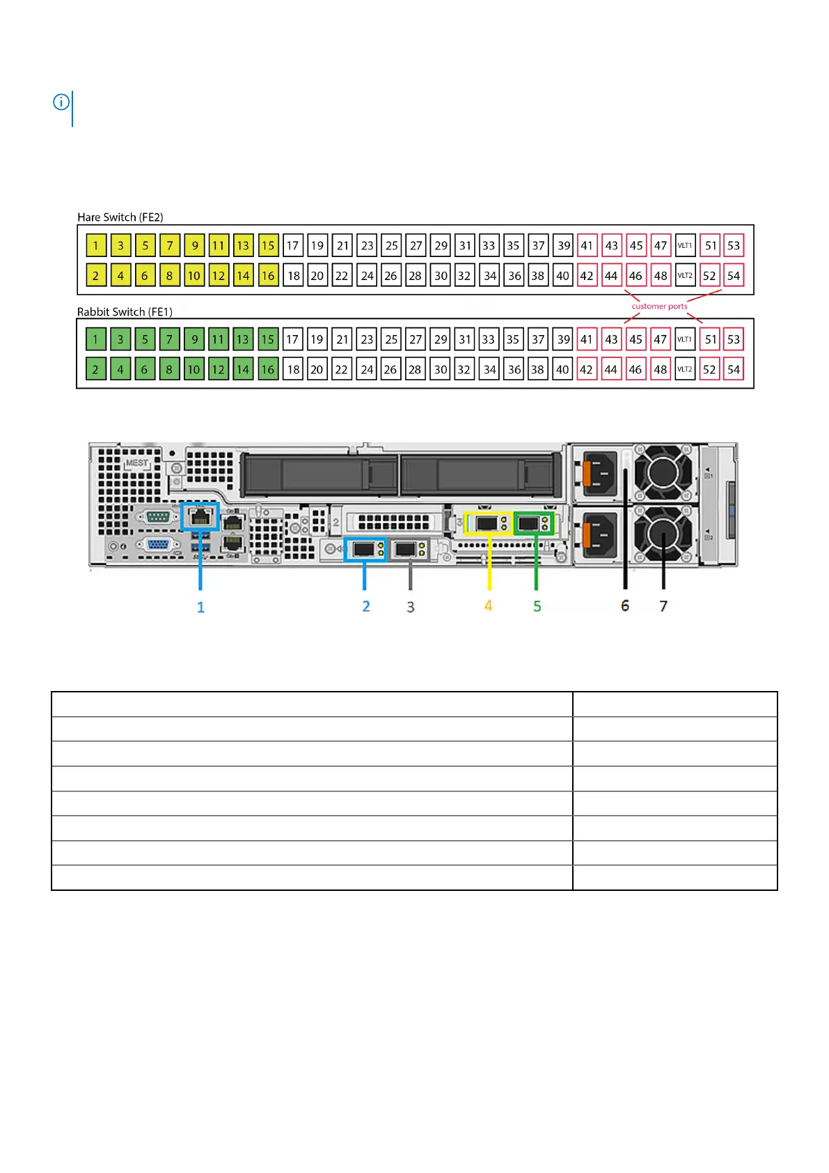
The numbered front-end switch ports used for connecting to the ports on the EX500 nodes are shown in the following diagram.
Port 1 on the Hare switch (FE2) connects to port 4 on Node 1. Port 2 on the Hare switch (FE2) connects to port 4 on Node 2,
and so on. Similarly, Port 1 on the Rabbit switch (FE1) connects to port 3 on Node 1. Port 2 on the Rabbit switch (FE1) connects
to port 3 on Node 2, and so on.
Figure 58. Node ports on front-end switches
Figure 59. Network cable and labeling
In the table below, x is the server number.
Network Cable Description
Labeling
1 - iDRAC management port, back-end switch 1 Server x iDRAC *
2 - Back-end switch 1 Server x BE 1 *
3 - Back-end switch 2 Server x BE 2 *
4 - Front-end switch 2 Server x FE 2 *
5 - Front-end switch 1 Server x FE 1 *
6 - Power cable (black) AC PS1
7 - Power cable (grey) AC PS2
The numbered back-end switch ports used for connecting to the ports on the EX500 nodes are shown in the following diagram.
Port 1 on the Hound switch (BE2) connects to port 2 on Node 1. Port 2 on the Hound switch (BE2) connects to port 2 on Node
2, and so on. Similarly, Port 1 on the Fox switch (BE1) connects to port 1 on Node 1. Port 2 on the Fox switch (BE1) connects to
port 1 on Node 2, and so on.
EX500 Platform
85
 Loading...


