Wiring ASDA-B2-F
3-16 September, 2015
3
3.3.2 Signals Explanation of Connector CN1
The following details the signals listed in previous section:
General Signals
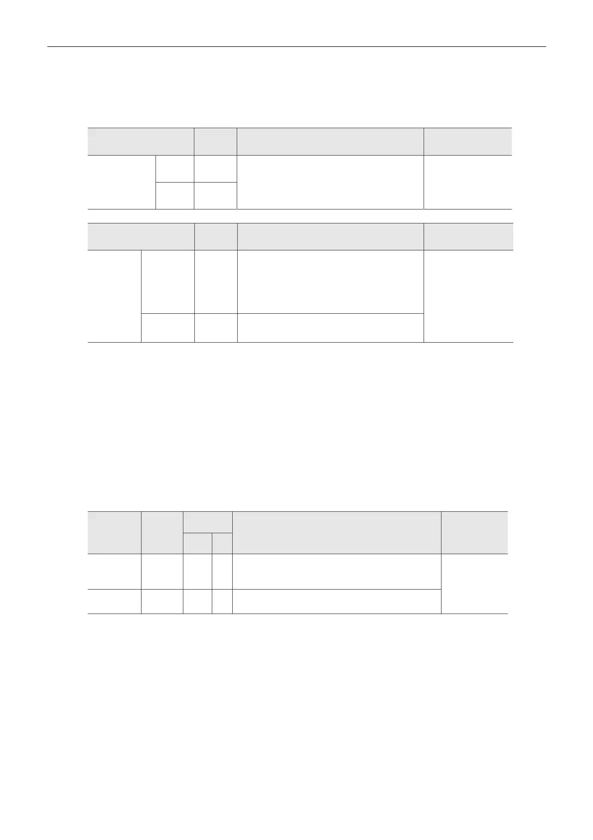
Signal Pin No Function
Wiring Method
(Refer to 3.3.3)
Position Pulse
(Output)
OA
/OA
7
8
Encoder signal output A and B (Line Drive
output)
C5/C6
OB
/OB
9
10
Signal Pin No Function
Wiring Method
(Refer to 3.3.3)
Power
COM+ 11
The positive end of the external power
(+12 V ~ +24 V) must be connected to
COM+. COM+ is the common input of digital
input.
-
GND 6 Power of Control Panel 0 V
There are various operation modes available in this servo drive (please refer to Chapter 6.1) and
each mode requires different I/O signal configuration. Thus, programmable I/O signals are
provided. That is, users are able to choose DI and DO signals to meet different application
requirements. Basically, default setting of DI/DO signal has already have the appropriate function
which can satisfy the demand of general application.
Refer to the following DI/DO table to know the corresponding default setting of DI/DO signal and
Pin No of the selected mode in order to conduct the wiring.
The explanation of DO signal default setting is as follows.
Do Signal
Name
Operation
Mode
Pin No
Function
Wiring Method
(Refer to 3.3.3)
+ -
SRDY ALL - -
When the servo drive applies to the power and no
alarm (ALRM) occurs in control circuit and motor
power circuit, this DO is ON.
C1,C2
ZSPD ALL - -
When the motor speed is slower than the setting
value of parameter P1-38, this DO is ON.
Note:
1. For example, if Sz mode is selected, pin 3 and 2 are defined as DO.TSPD.
2. The unlisted Pin No means the signal is not the preset one. If users want to use it, parameters need to
be changed and set as the desired ones. Please refer to Section 3.3.4 for further detail.

 Loading...


