Wiring ASDA-B2-F
3-18 September, 2015
3
3.3.3 Wiring Diagrams (CN1)
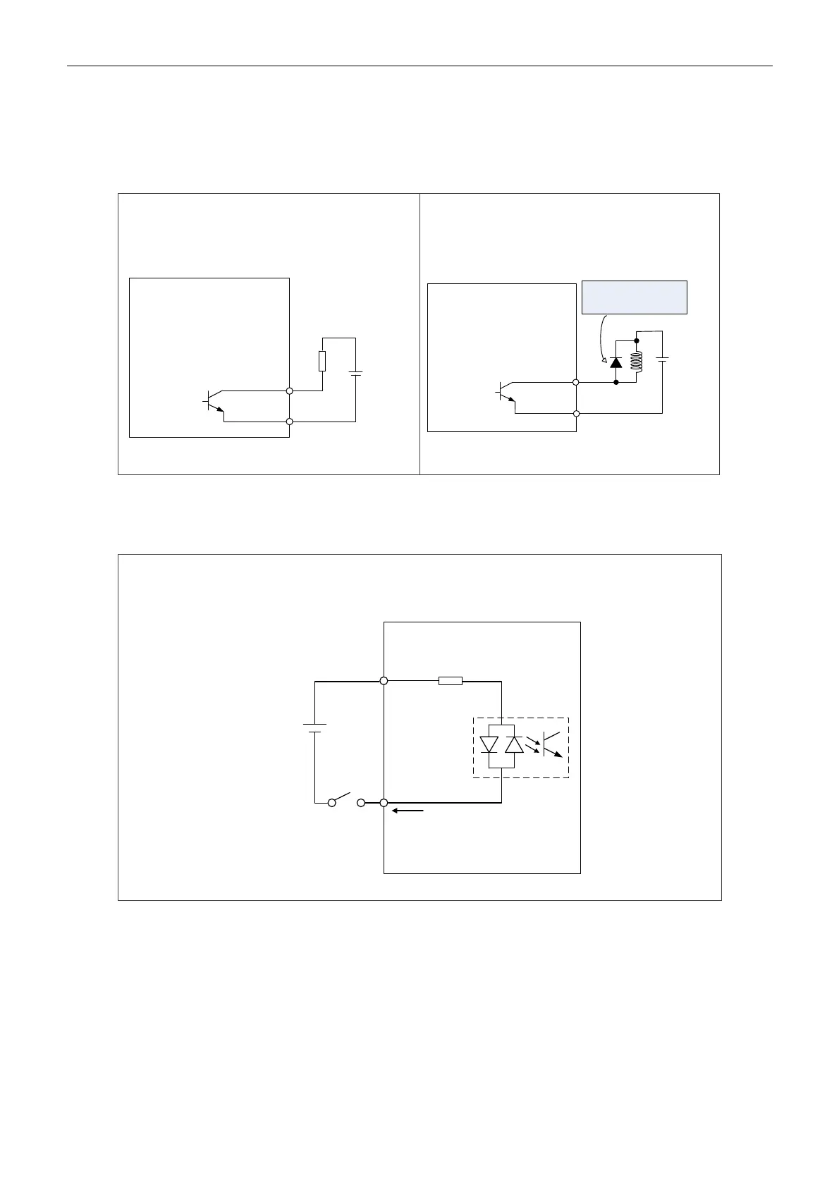
When the drive connects to inductive load, the diode has to be installed. (The permissible current
is under 40 mA. The surge current is under 100 mA.)
C1: Wiring of DO signal. The servo drive applies to
the external power and the resistor is general load.
R
24 V
DC
DOX-
Servo Drive
DOX+
DO1: (12,13)
DO2: (14,15)
DOX: (DOX+,DOX-)
X = 1,2
24 VDC
50 mA
C2: Wiring of DO signal. The servo drive applies to
the external power and the resistor is inductive
load.
DOX-
Servo Drive
DOX+
DO1: (12,13)
DO2: (14,15)
DOX: (DOX+, DOX-)
X = 1,2
Ensure the polarity (+, -)
of diode is correct or it
may damage the drive.
24 VDC
Input signal via relay or open-collector transistor
NPN transistor, common emitter (E) mode (SINK mode)
C3:The wiring of DI. The servo drive applies to the external power.
24 V
DC
SON
COM+
Servo Drive
Approx. 4.7 KΩ

 Loading...


