ASDA-B2-F Panel Display and Operation
September, 2015 4-7
4
4.3.4 Positive and Negative Sign Setting
Displayed Symbol Description
When entering the Editing Setting Mode, pressing the UP / DOWN Key can
change the displayed value. The SHIFT Key can change the carry value users
wish to alter. (The carry value is flashing at the moment.)
Pressing the SHIFT Key for two seconds can switch the positive (+) and negative
(-) sign. If the parameter value is over the range after switching the positive or
negative sign, then it cannot be switched.
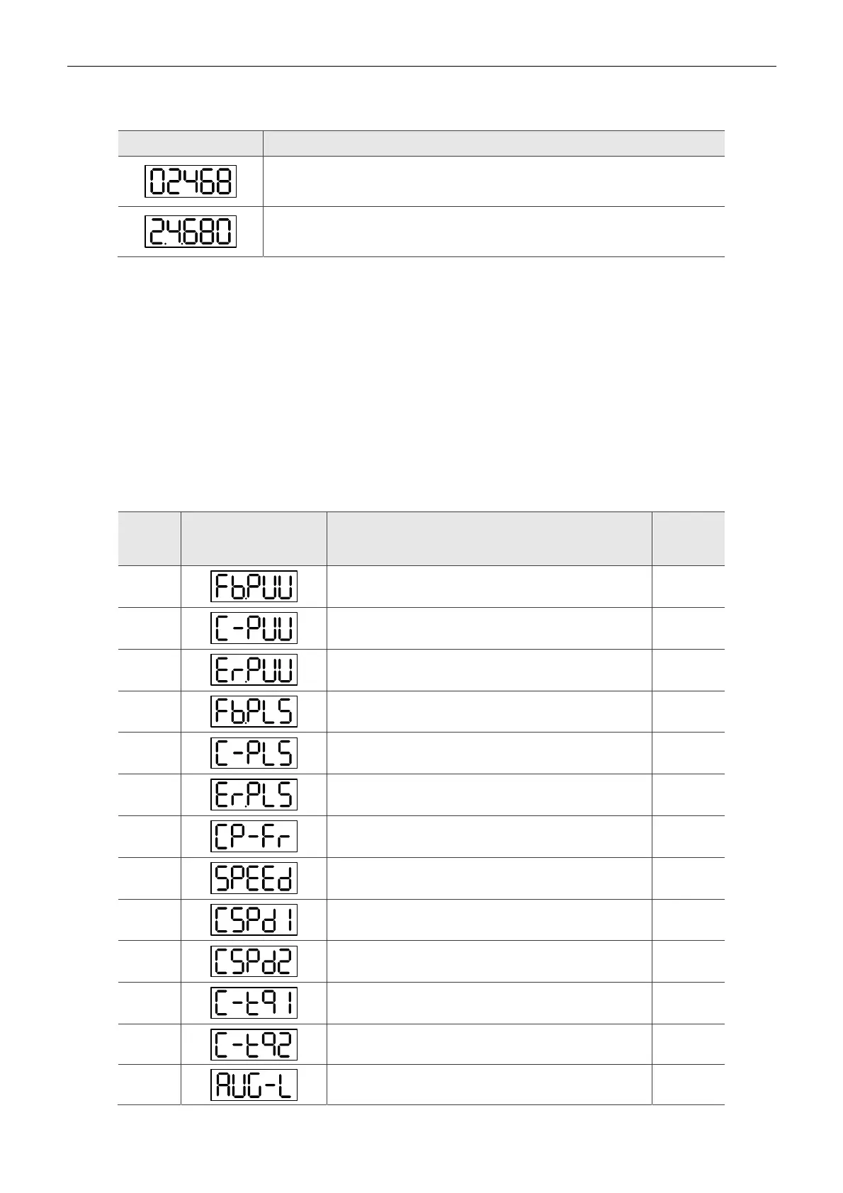
4.3.5 Monitor Display
When the drive is applied to the power, the display will show the monitor displayed symbol for a
second, and then enter Monitoring Mode. In Monitoring Mode, the UP / DOWN Key can change
the monitoring variable. Or, the user can directly change parameter setting of P0-02 to set the
monitoring code. When applying to the power, the system will pre-set the monitoring code
according to the setting value of P0-02. For example, the setting value of P0-02 is 4. Every time
when applying to the power, it will display C-PLS monitor sign first, and then shows the input
pulse number of pulse command.
P0-02
Setting
Value
Monitor Displayed
Symbol
Description Unit
0
Motor feedback pulse number (after the scaling of
electronic gear ratio) (User unit)
[user unit]
1
Input pulse number of pulse command (after the scaling
of electronic gear ratio) (User unit)
[user unit]
2
The difference of error pulse number between control
command pulse and feedback pulse number (User unit)
[user unit]
3
Motor feedback pulse number (encoder unit) (1.28
million Pulse/rev)
[pulse]
4
Input pulse number of pulse command (before the
scaling of electronic gear ratio) (encoder unit)
[pulse]
5
Error pulse number (after the scaling of electronic gear
ratio) (encoder unit)
[pulse]
6
Input frequency of pulse command [Kpps]
7
Motor speed [r/min]
8
Speed input command [Volt]
9
Speed input command [r/min]
10
Torque input command [Volt]
11
Torque input command [%]
12
Average torque [%]

 Loading...


