Control Mode of Operation ASDA-B2-F
6-6 September, 2015
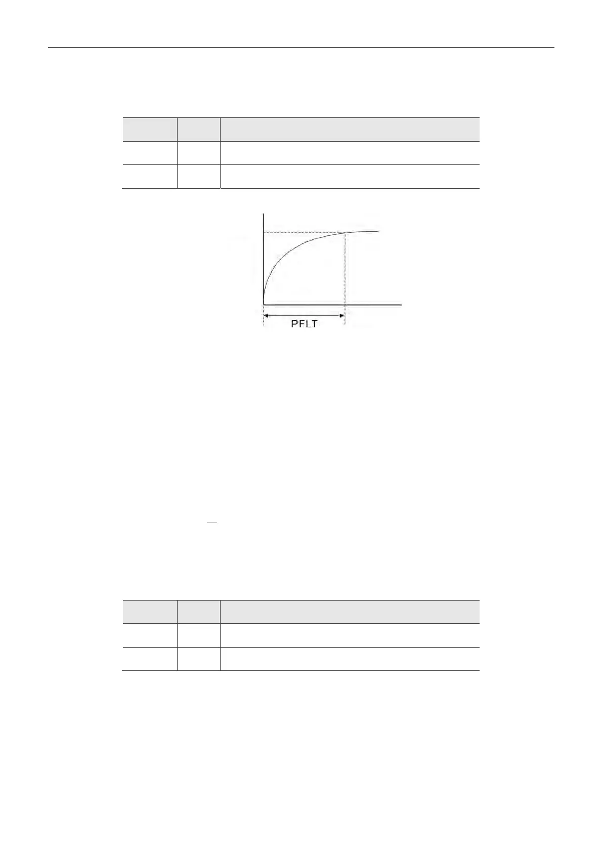
6.2.4 Low-pass Filter
Relevant Parameters (Please refer to Chapter 7 for detailed description):
Parameter Abbr. Function
P1-08 PRLT Smooth Constant of Position Command (Low-pass Filter)
P1-45 GR2 Gear Ratio (Denominator) (M)
6.2.5 Gain Adjustment of Position Loop
Before setting the position control unit, users have to manually complete the setting of tuning
mode selection (P2-32) since the speed loop is included in position loop. Then, set the position
loop gain (P2-00) and position feed forward gain (P2-02). Users also can use the auto mode to
automatically set the gain of speed and position control unit.
1. Proportional gain: Increase the gain so as to enhance the response bandwidth of position
loop.
2. Feed forward gain: Minimize the deviation of phase delay.
The position loop bandwidth cannot exceed the speed loop bandwidth. It is suggested that:
4
fv
fp
. fv: response bandwidth of speed loop (Hz).
KPP = 2 × × fp. fp: response bandwidth of position loop (Hz).
For example: the desired position bandwidth is 20 Hz KPP = 2 × × 20= 125.
Relevant Parameters (Please refer to Chapter 7 for detailed description):
Parameter Abbr. Function
P2-00 KPP Position Loop Gain
P2-02 PFG Position Feed Forward Gain
Target Position

 Loading...


