5 Planning the installation
Installation and Operation Manual for RPI M6A M8A M10A inverters V1.0 2016-02-03
32
5.10 Dry contacts
The inverter supports one multi-function relay which can be used
for external alarm devices like buzzers or strobe lights.
On the display (see “8.9 Dry contacts”, p. 80), the dry contacts
can be connected to one of the following events:
Event Description
Disabled
The functionality for dry contacts is
switched off.
On Grid The inverter has connected to the grid.
Fan Fail The fans are defective.
Insulation Insulation test failed.
Alarm
An error, fault, or warning message
occurred.
Error An error message occurred.
Fault A fault message occurred.
Warning A warning message occurred.
Default setting for both dry contacts is “Disabled”.
Cable and wire requirements
● Twisted and shielded cable (CAT5 or CAT6) with 2 wires
● Cable diameter: 5 mm
● Wire cross section: 1 mm
2
● The RS485 cables should be kept separate from the AC
cable and the DC cables to avoid interferences
Providing 12 V
DC
supply power for an external alarm device
Depending on the type of communication card, the inverter pro-
vides one or two sources of on-board 12 V
DC
power supplies.
Source of
supply power
Supply
voltage
Communication card
Type 1 Type 2
a)
Communication
card
12 V
DC
not possible x
b) RS485 card 12 V
DC
x x
1)
1) not recommend as it is more complicated than variant a)
Check the type of communication card installed in your inverter
before you plan how to connect dry contacts and digital inputs.
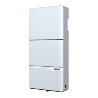
Dry contacts
Digital inputs and
External Power Off
Fig. 5.17: Communication card type 1
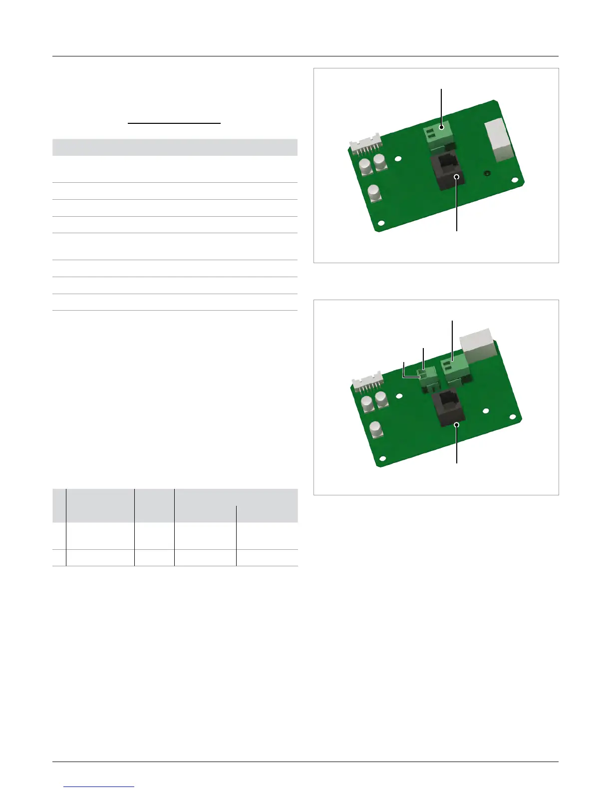
VCC
Dry contacts
Digital inputs and
External Power Off
GND
Fig. 5.18: Communication card type 2
 Loading...