8 Settings
Installation and Operation Manual for RPI M6A M8A M10A inverters V1.0 2016-02-03
96
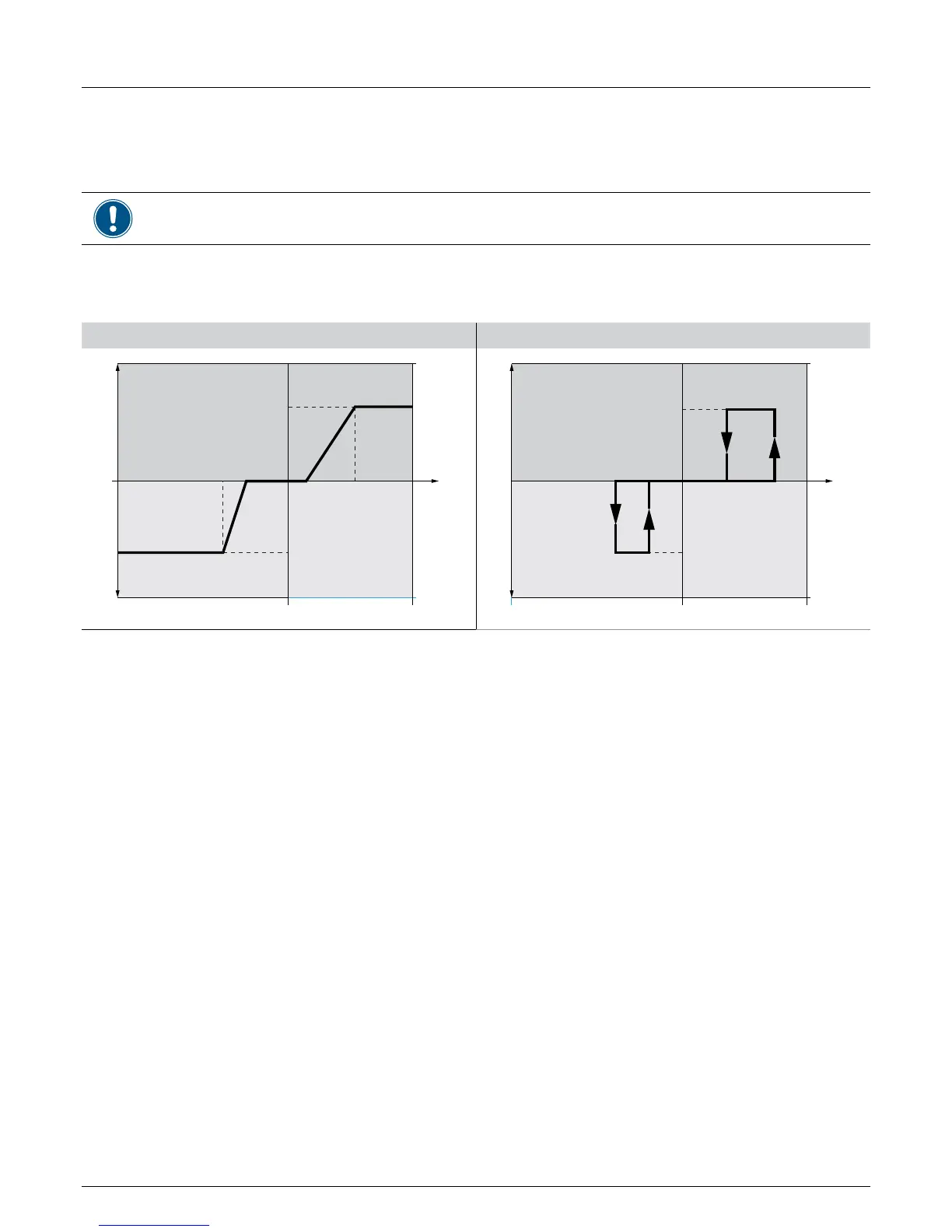
8.19 Q (V) - Apparent power versus voltage
Overview
Values have been set based upon country standards. If you modify these values, you will lose certication. Therefore you
should set this function only when requested by country regulations, authorities or your grid operator.
With this function you can set the apparent power as a function of the grid voltage.
This function is available for medium voltage grids only.
(1) Behavior for Curve A (2) Behavior for Curve B
V
1s
V
2s
V
1i
V
2i
264.5 V230.0 V
63%
63%
V
184.0 V
Q
s limit
Q
i limit
Q inductiveQ capacitive
V
1s
V
2s
V
1i
V
2i
V
264.5 V230.0 V
63%
63%
184.0 V
Q
s limit
Q
i limit
inductive cos φ
Q inductiveQ capacitive
Operating behavior for curve A
When the grid voltage increases to the lower voltage limit V1s, the inverter starts to feed-in inductive reactive power. When you set the
parameter T inductive, the inverter will wait for this period time for the grid voltage falling back to a level below V1s before it starts feed-
ing in inductive reactive power. When the grid voltage continues to increase, the inductive reactive power will be increased according
to the ramp dened by the curve. If the grid voltage exceeds the upper voltage limit V2s, the inductive active power remains at the level
dened in Qs limit.
When the grid voltage falls to the upper voltage limit V1i, the inverter starts to feed-in inductive reactive power. When you set the
parameter T delay, the inverter will wait for this period time for the grid voltage rising back to a level above V1i before it starts feeding
in inductive reactive power. When the grid voltage continues to fall, the inductive reactive power will be increased according to the ramp
dened by the curve. If the grid voltage exceeds the upper voltage limit V2i, the inductive active power remains at the level dened in
Qi limit.
Do not change this setting without prior
consultation with Delta Solar Support.
 Loading...