1 About this manual
Installation and Operation Manual for RPI M6A M8A M10A inverters V1.0 2016-02-03
6
1.4 Conventions used in this manual
Order of instructions
Numbered instructions must be performed in the specied order.
1. First instruction step
→ When the inverter reacts to a step, this reaction is
marked with an arrow.
2. Second instruction step
3. Third instruction step
Instructions consisting of only one step or when the order of the
instruction steps is not important, are shown as follows:
► Instruction step
► Instruction step
Marking of inverter parts
Parts of the inverter are marked as follows:
Buttons:
ESC
button
LEDs on the inverter:
LED
All other parts: RS485 terminal.
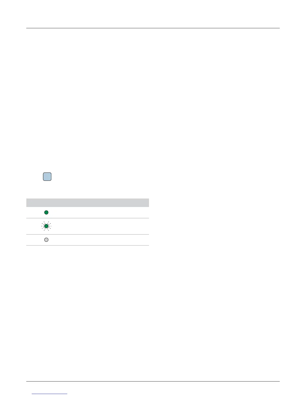
LED symbol Meaning
LED stays on.
LED ashes.
LED is off.
Information on Display
Information shown on the inverter display includes menus, set-
tings and messages.
This information is shown in this manual as follows:
Menu names: User settings menu
Parameter names: Cos phi parameter
 Loading...