SIRIUS®
8.2.1 Synchronisation Glossary
8.2.1.1 Sampling
The analogue signals that we want to measure are
continuous time signals. Since all computer based systems
are digital, we need to convert those continuous time
signals to discrete time signals: this process is called
sampling.
A sample refers to a value at a point in time.
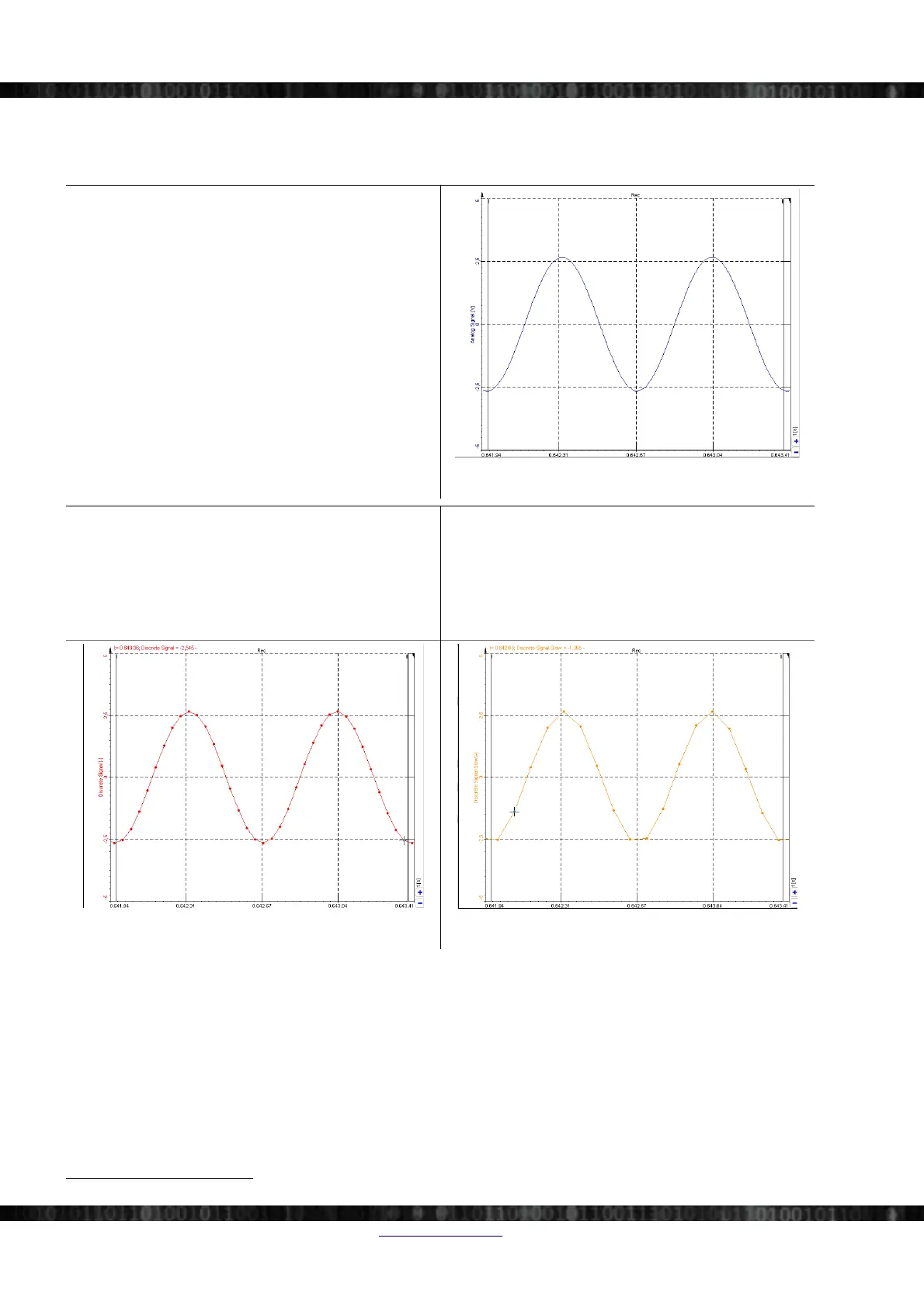
The Illustration 215 shows the continuous analogue
signal.
Illustration 215: Continuous signal
Illustration 216 below shows the sampled version of the
signal in Illustration 215. The actual data consists only of
the sampled points that you see as red dots in the diagram.
The lines in between the points are just interpolated.
Illustration 217 below shows another sampled version of
the signal in Illustration 215. But in comparison to
Illustration 216 we used a lower sample rate in this case.
Because of the lower sample rate, we have fewer data
points acquired and thus the interpolated signal does not
resemble the original signal as good as Illustration 216
does.
Illustration 216: Sampled (discrete) signal
Illustration 217: Slower sampled (discrete) signal
The sampling rate (aka. sample rate, sampling frequency) defines the number of samples per second taken from the
continuous signal to create the discrete signal. The unit for the sampling rate is hertz (Hz) .
The inverse of the sampling frequency is the sampling period or sampling interval, which is the time between samples.
8.2.1.2 Clock
A clock signal is a particular type of signal that oscillates between a high and a low state and is utilized like a
metronome to coordinate actions.
E.g. each SIRIUS® chassis has an internal clock. The sampling of the data-points is always correlated to this clock – so
that the data-points of all channels (on all modules) refer to the same point in time
25
.
25 Like all real-world devices also the clock generator of SIRIUS® is not ideal. But this is negligible related to the sample rates.
Page 150/166 www.dewesoft.com Doc-Version: 1.4.2