Enclosure Overview
Since there are 2 connectors it's easy to chain several SIRIUS® chassis (or DEWE-43, DS-CAN2, etc.) together.
Note that there is no distinction between IN and OUT – it does not matter which connector you use.
4.2.1.3 USB
The USB connector is used to transfer the measurement data from the SIRIUS® device to the measurement PC.
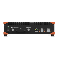
4.2.1.4 Power In
Illustration 50: Power In
Connector 2pin
Pin Name
For the power supply an unregulated DC voltage between 6
and 36 Volts is required, which is connected to LEMO 1B
connector on the rear side of the chassis.
Power In connector (on the device): EXJ.1B.302.CLA
Mating connector (for the cable): FGJ.1B.302.CLLD52Z
1 V+
2 V-
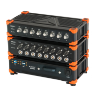
4.2.1.5 Power Out
Illustration 51: Power Out
Connector 2pin
Pin Name
The Power Out power plug that can be used to chain several
chassis together.
Power Out connector (on the device): EXG.1B.302.CLL
Mating connector (for the cable): FGG.1B.302.CLAD52Z
1 V+
2 V-
4.2.1.6 GND connector
See connector GND in Illustration 47 on page 26.
For correct measurements, it is highly recommended to ground the SIRIUS® with GND banana plug on the rear side.
WARNING
It is mandatory to connect a ground cable to the GND connector of the SIRIUS® when you
are working with high voltages: e.g. when you are working with the HV modules (see 5.9 HV
on page 62).
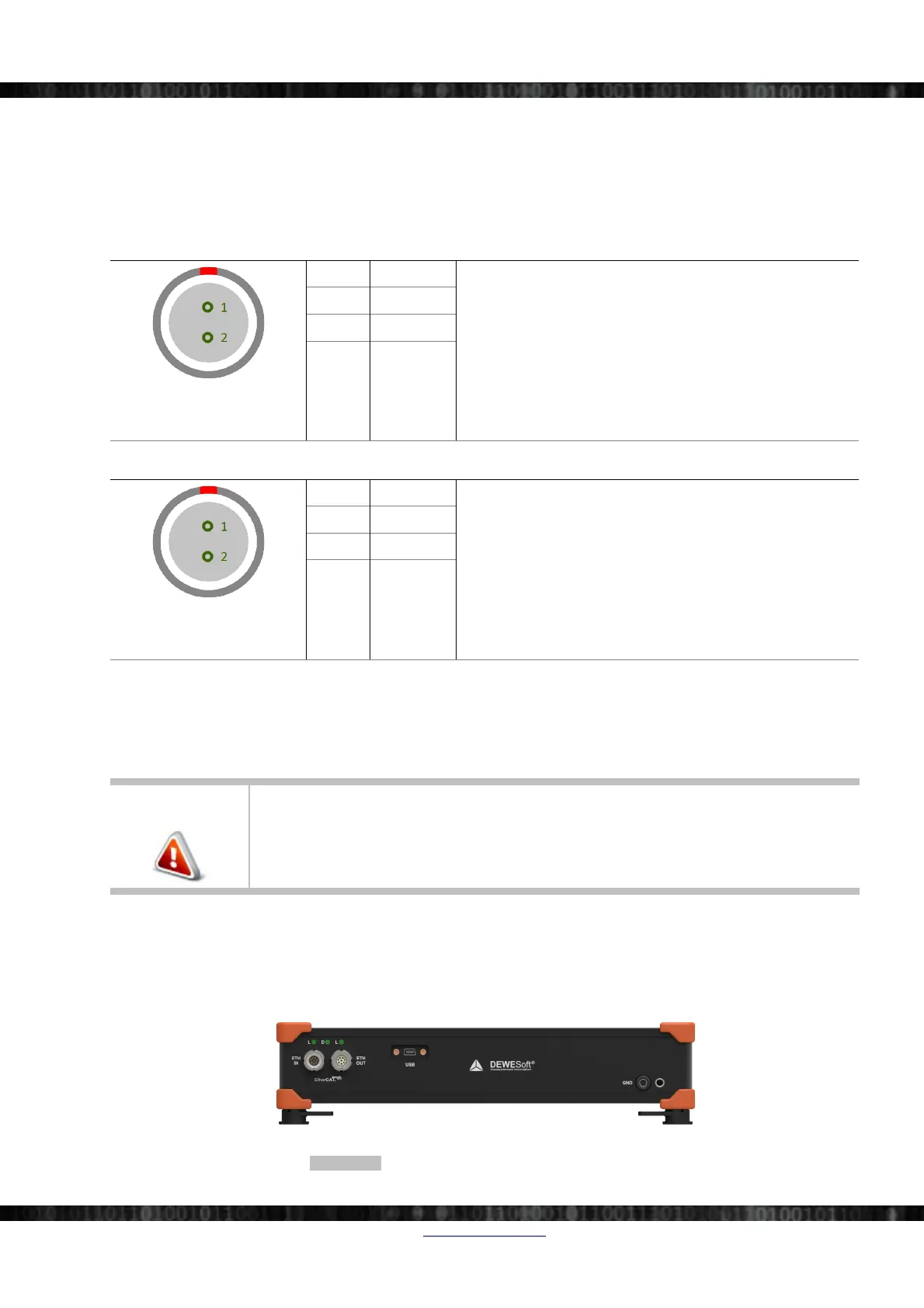
4.2.2 Single Slice Version EtherCAT®
This chapter describes the connectors on the rear side of the SIRIUS® EtherCAT® slices (see also 5.1.2 EtherCAT® on
page 47):
Illustration 52: SIRIUS® EtherCAT® rear side connectors
Doc-Version: 1.4.2 www.dewesoft.com Page 27/166
 Loading...