EPSON LX-300+II/300+II RTP/1170II Revision D
LX-300+II RTP DISASSEMBLY AND ASSEMBLY 101
7.1.3 Printer Mechanism Removal
1. Remove the upper housing. (See 7.1.2 “Upper Housing Unit Removal”.)
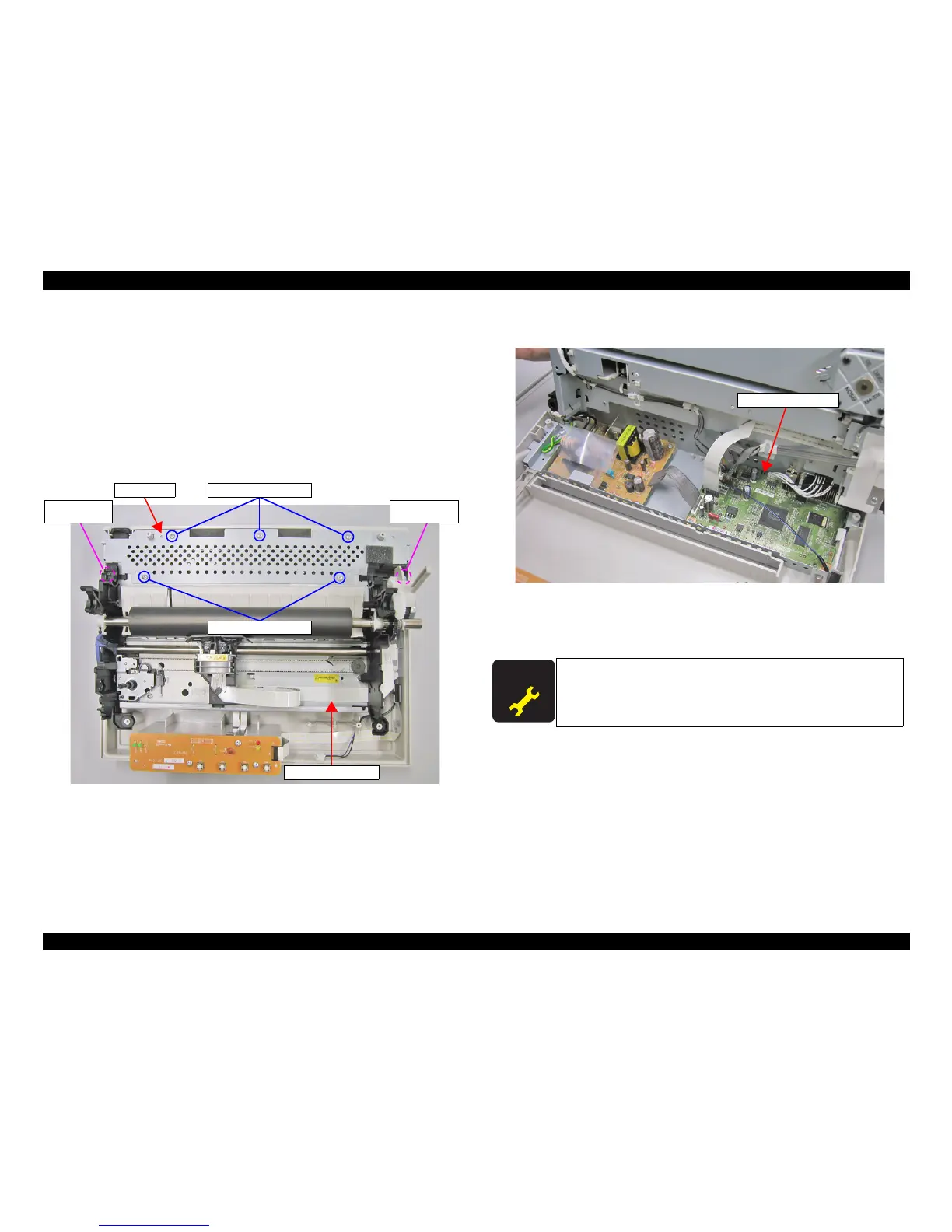
2. Remove 3 screws (C.B.P., Tite, 3x10 F/ZN;Torque 0.78-0.98 N.M.) and 2 screws
(C.B.S., Screw, 3x4 F/Zn;Torque 0.78-0.98 N.M.) securing the upper shield plate
to the lower housing.
3. Remove the shield cover.
4. Remove 2 screws with washers (C.B.B., (W(13), 3x14 F/ZN) securing the printer
mechanism to the lower housing.
Figure7-4. Shield Cover
5. Lift the printer mechanism a little bit and remove the harnesses from the main board
assembly.
Figure7-5. Harness Removal
6. Remove the printer mechanism.
When the printer mechanism is removed, perform the Bi-D
adjustment.
When the printer mechanism is replaced, perform the Bi-D
adjustment, top margin adjustment, and bottom margin adjustment.
 Loading...