____________________________________________________________________
Page 5-86 G1000 System Maintenance Manual
Rev. A 190-00903-00
5.1.8.7 GEA Configuration Page
CAUTION
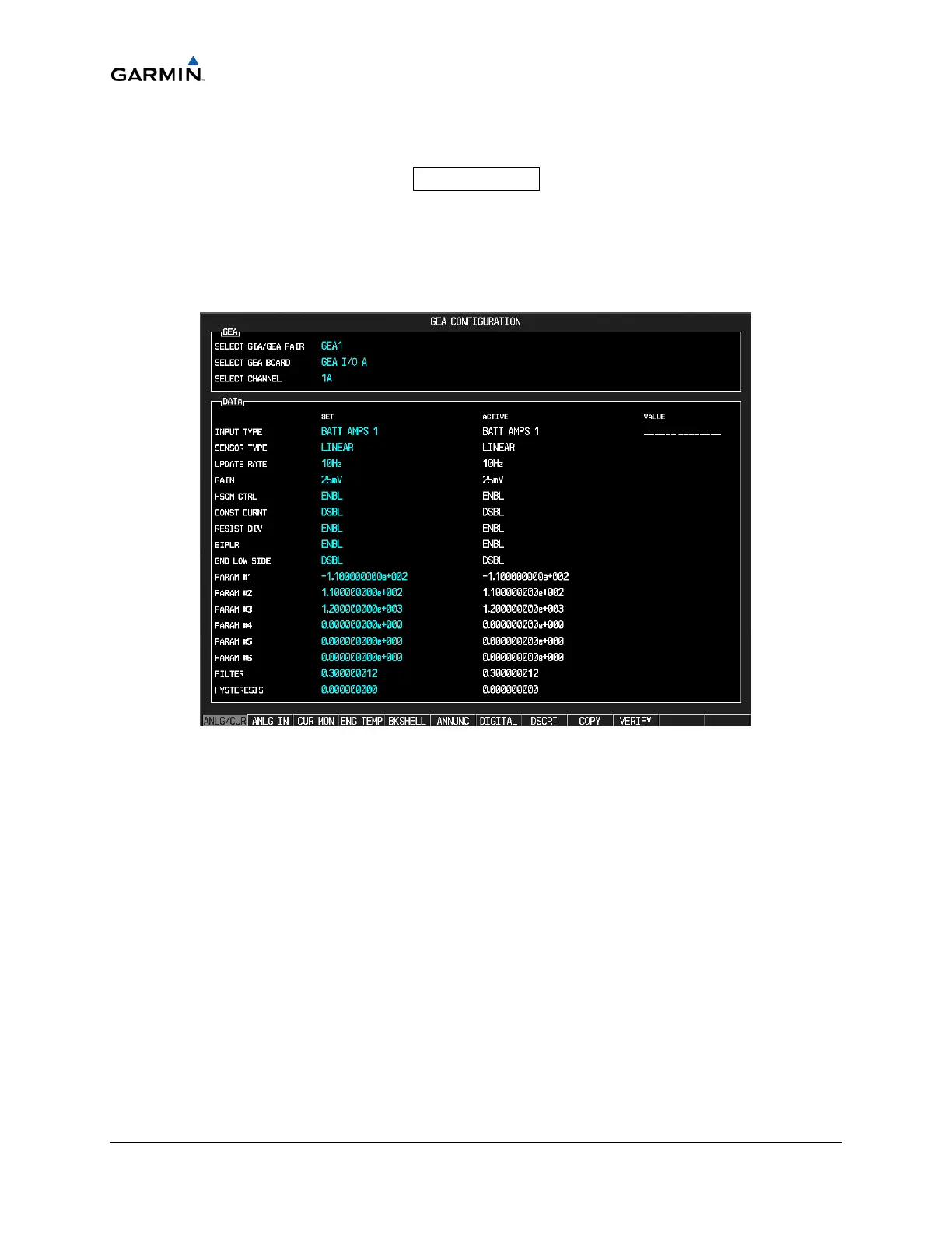
The data contained on the GEA Configuration Page (Figure 5-18) is
extremely critical to aircraft safety. Although the content can be viewed,
the technician cannot make changes unless authorized and equipped to do
so.
Figure 5-12. GEA Configuration Page
These pages show configuration settings for all inputs/outputs of the GEA 71 Engine/Airframe
Unit. All settings are pre-established for a particular installation and are loaded from the
appropriate G1000 Loader Card. Input/Outputs are categorized by groups and are brought on-
screen by the pressing appropriate softkey. All settings are contained in the ‘GEA 1’
configuration file.
GEA―This box indicates which GEA, GEA circuit board, and/or GEA I/O channel is currently
selected for display.
DATA―This box displays current configuration settings for the selected inputs/outputs in the
GEA window.
SOFTKEYS:
a. ANLG/CRNT―Displays analog/current configuration settings.
b. ANLG IN―Displays analog in configuration settings.
c. CRNT MON―Displays current monitor configuration settings.
d. ENG TEMP―Displays engine temperature sensor configuration settings.

 Loading...


