190-02692-00 Rev. A
Garmin G100 Pilot’s Guide for the Piper PA-32 Saratoga
46
FLIGHT INSTRUMENTS
SYSTEM
OVERVIEW
FLIGHT
INSTRUMENTS
EIS
AUDIO PANEL
& CNS
FLIGHT
MANAGEMENT
HAZARD
AVOIDANCE
AFCS
ADDITIONAL
FEATURES
APPENDICESINDEX
2.1 FLIGHT INSTRUMENTS
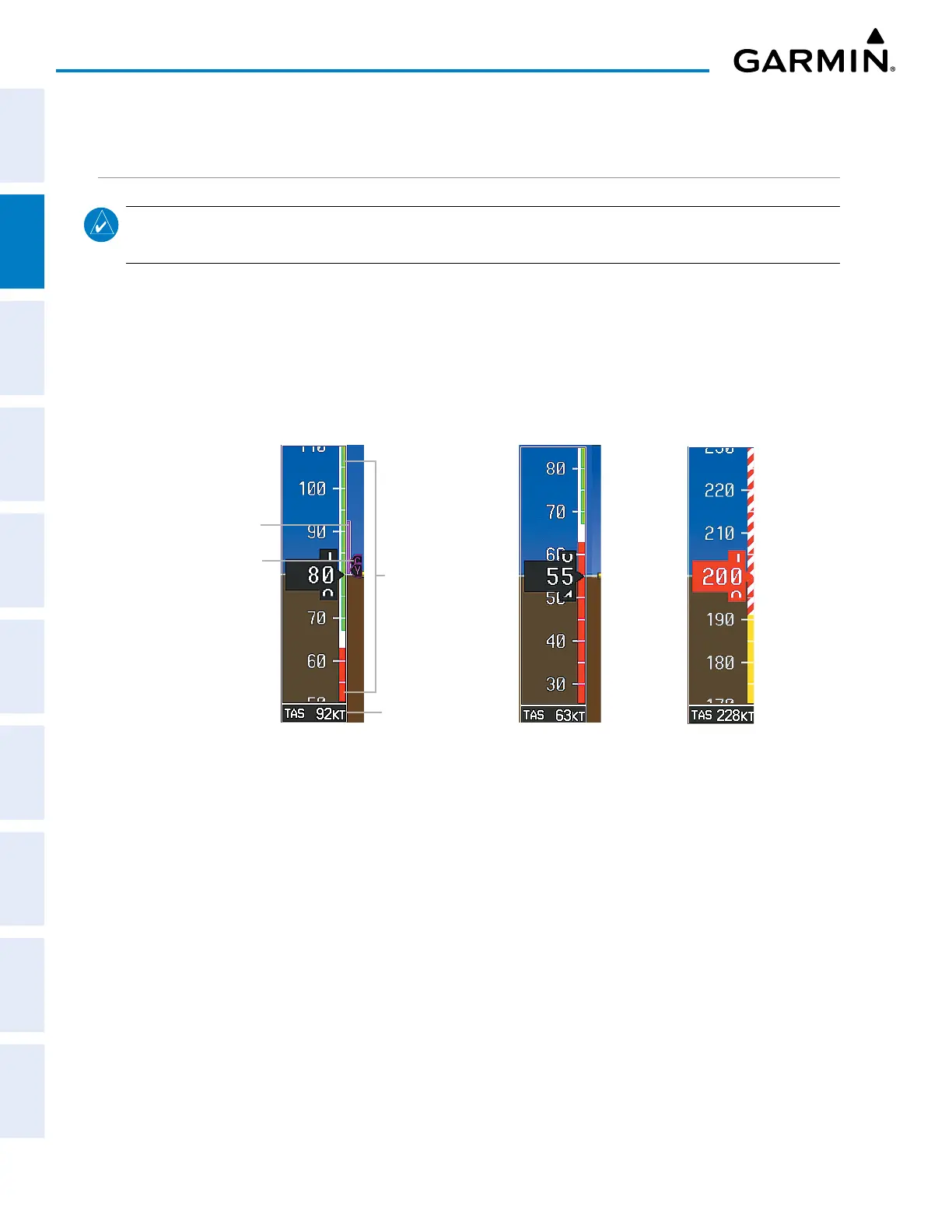
AIRSPEED INDICATOR
NOTE: Refer to the current version of the pertinent flight manual for airframe-specific airspeed criteria and
Vspeed values.
The Airspeed Indicator displays airspeed on a moving tape rolling number gauge. The true airspeed (TAS)
is displayed in knots below the Airspeed Indicator. The numeric labels and major tick marks on the moving
tape are marked at intervals of 10 knots. The minor tick marks on the moving tape are marked at intervals of
5 knots. Speed indication starts at 20 knots, with 60 knots of airspeed viewable at any time. The indicated
airspeed is displayed inside the black pointer. The pointer remains black until reaching maximum operating
speed (V
NE
), at which point appears red.
Operating Ranges
Airspeed Trend Vector
Vspeed Reference Bug
True Airspeed
Speed Ranges
Low Speed Range
Red Pointer at V
NE
Figure 2-3 Airspeed Indicator
Color coded stripes appear on the Airspeed Indicator to show the operating ranges. The low speed range
stripe is red. Normal operating range is green, caution range is amber, and the never exceed speed (V
NE
) begins
with a red and white barber pole. A white stripe indicates the flaps operating range.
The Airspeed Trend Vector is a vertical magenta line, extending up or down the airspeed scale to the right of
the speed range. The end of the trend vector indicates the predicted airspeed in six seconds if the current rate of
acceleration is maintained. If the trend vector crosses V
NE
, the number in the indicated airspeed pointer changes
to amber. The trend vector is absent if the speed remains constant or if any data needed to calculate airspeed is
not available due to a system failure.
Vspeeds (Glide, V
x
, V
y
, and V
r
) can be changed and their bugs turned on/off from the Timer/References
Window. When active (ON), the Vspeeds are displayed to the right of the airspeed scale. On the next avionics
power cycle, Vspeeds return to their default values. When the indicated airspeed is below 20 knots, enabled
Vspeed bugs and their numeric values appear in a list at the bottom of the airspeed tape, ordered from highest
to lowest.
 Loading...


