Field replaceable units: Replace display assembly parts
7-30 Dash 3000/4000/5000 2000966-542D
Replace keypad assembly or Trim Knob control
Follow the steps below for the patient monitor you are servicing.
Dash 3000 patient monitor
with display shield flex circuit
Dash 4000 patient monitor Dash 5000 patient monitor
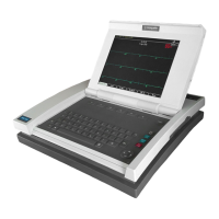
1. Remove the rubber knob from the Trim
Knob control shaft.
1. Remove the rubber knob from the Trim
Knob control shaft.
1. Remove the rubber knob from the Trim
Knob control shaft.
2. Use an 11mm wrench or nut driver to
remove the nut holding the Trim Knob
control’s shaft to the display bezel.
2. Use an 11mm wrench or nut driver to
remove the nut holding the Trim Knob
control’s shaft to the display bezel.
2. Open the display assembly. Refer to
page 7-27.
3. Open the display assembly. Refer to
page 7-27.
3. Open the display assembly. Refer to
page 7-27.
4. Remove the three screws holding the
keypad assembly to the display bezel.
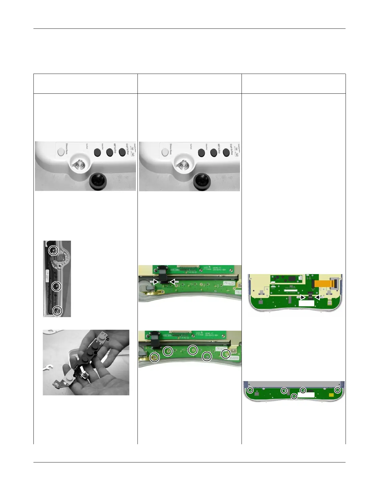
4. Follow these steps to remove the
keypad assembly from the front bezel:
a. Gently squeeze the latch release and
pull up to disconnect the keypad cable
from the keypad PCB.
b. Remove the five screws holding the
keypad assembly to the front bezel.
c. Lift the mounting plate. Refer to steps
4b and 4c on page 7-31.
3. Remove the keypad assembly from the
front bezel.
a. Gently squeeze the latch release and
pull up to disconnect the keypad cable
from the keypad PCB. Disconnect the
display flex.
b. If required, lift the mounting plate off
the display bezel bosses to provide
access to the keypad mounting
screws.
c. Remove the five screws holding the
keypad assembly to the front bezel,
and remove the keypad assembly.
5. Place the new keypad assembly in the
display bezel.
5. Place the new keypad assembly in the
display bezel.
4. Place the new keypad assembly in the
display bezel.
6. Reattach the keypad cable. 6. If required, replace the grounding strap. 5. Reattach the keypad cable.
Keypad Assembly
three screws
590A
591A
 Loading...