3.1.1.1 TIMING OF THE PHASE SELECTOR SIGNALS
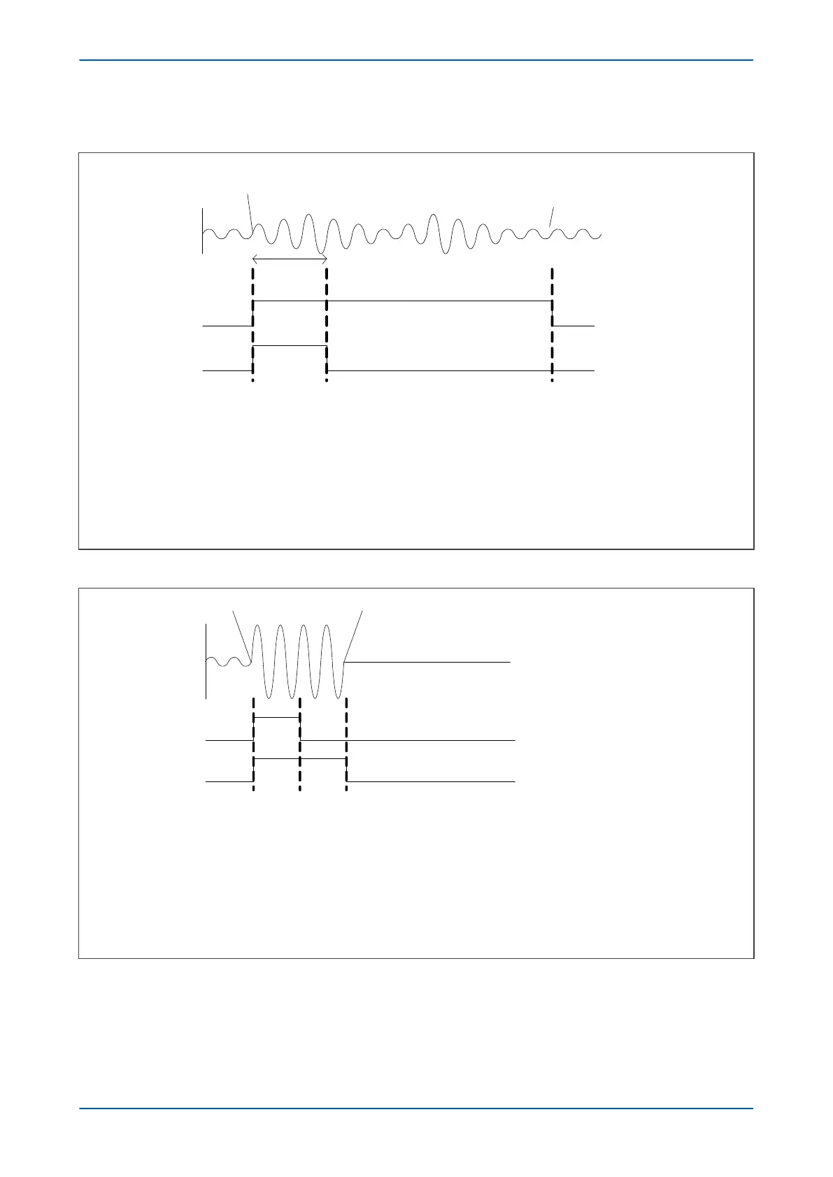
Start of
power swing
i (t)
3 cycles
PH1
PH2
t1: D i exceeds threshold 1 (5%In), so PH1 and PH2 go high
t
2
: Threshold 2 invoked. PH2 goes low on account of threshold being increased . PH1 remains high,
because there continues to be a D i
t
3
: PH1 goes low as power swing has diminished and D i goes below threshold 1
t1 t2
t
3
End of
power swing
V02769
Figure 118: Phase selector timing for power swing condition
Fault inception Fault cleared
i (t)
PH1
PH2
t
1
t
2
t
3
t
1
: D i exceeds threshold 1 (5%In), so PH1 and PH2 go high
t
2
: Fault current value appears in 2 cycle buffer . This equals present fault current value so D i is reduced to
zero. PH1 therefore goes low. PH2 remains high because value in PH 2 memory is a stored value .
t
3
: Fault is cleared so PH 2 goes low. PH1 stays low even though there is a new D I, because the absolute
current value is also taken into consideration .
V02770
Figure 119: Phase selector timing for fault condition
P446SV Chapter 10 - Power Swing Functions
P446SV-TM-EN-1 231