6.2 MAIN PROCESSOR BOARD
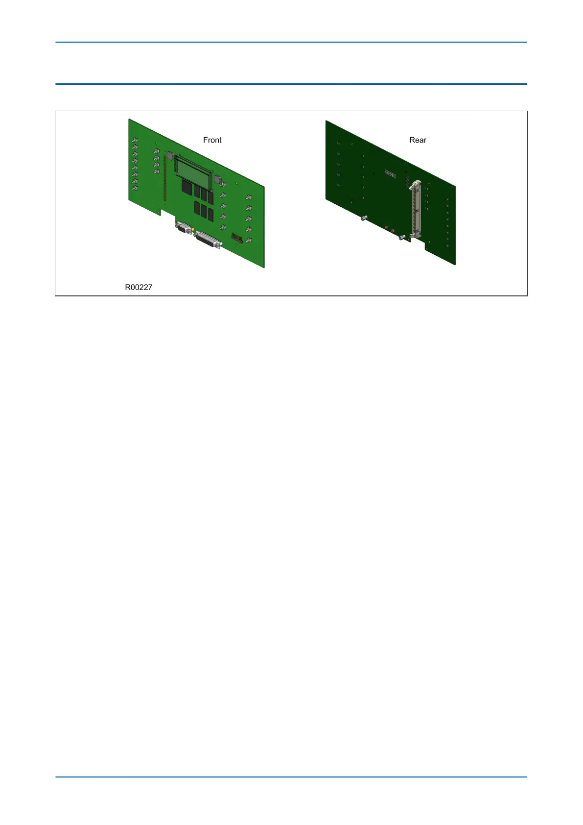
Figure 9: Main processor board
The main processor board performs all calculations and controls the operation of all other modules in the IED,
including the data communication and user interfaces. This is the only board that does not fit into one of the slots.
It resides in the front panel and connects to the rest of the system using an internal ribbon cable.
The LCD and LEDs are mounted on the processor board along with the front panel communication ports.
The memory on the main processor board is split into two categories: volatile and non-volatile. The volatile
memory is fast access SRAM, used by the processor to run the software and store data during calculations. The
non-volatile memory is sub-divided into two groups:
● Flash memory to store software code, text and configuration data including the present setting values.
● Battery-backed SRAM to store disturbance, event, fault and maintenance record data.
There are two board types available depending on the size of the case:
● For models in 40TE cases
● For models in 60TE cases and larger
Chapter 3 - Hardware Design P446SV
40 P446SV-TM-EN-1
 Loading...


