6.11 COPROCESSOR BOARD
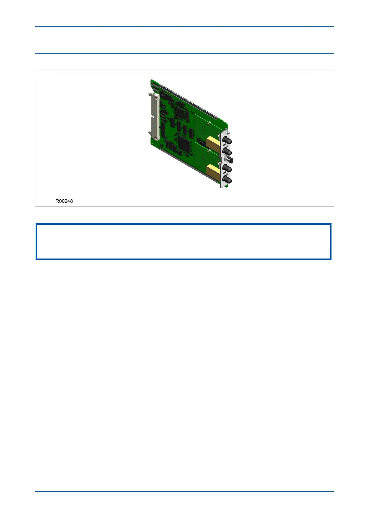
Figure 22: Fully populated Coprocessor board
Note:
The above figure shows a coprocessor complete with GPS input and 2 fibre-optic serial data interfaces, and is not necessarily
representative of the product and model described in this manual. These interfaces will not be present on boards that do not
require them.
Where applicable, a second processor board is used to process the special algorithms associated with the device.
This second processor board provides fast access (zero wait state) SRAM for use with both program and data
memory storage. This memory can be accessed by the main processor board via the parallel bus. This is how the
software is transferred from the flash memory on the main processor board to the coprocessor board on power
up. Further communication between the two processor boards is achieved via interrupts and the shared SRAM.
The serial bus carrying the sample data is also connected to the co-processor board, using the processor’s built-in
serial port, as on the main processor board.
There are several different variants of this board, which can be chosen depending on the exact device and model.
The variants are:
● Coprocessor board with current differential inputs and GPS input
● Coprocessor board with current differential inputs only
● Coprocessor board with GPS input only
6.11.1
COPROCESSOR BOARD WITH 1PPS INPUT
In some applications, where the communication links between two remote devices are provided by a third party
telecommunications partner, the transmit and receive paths associated with one channel may differ considerably
in length, resulting in very different transmission and receive times.
If, for example, Device A is transmitting to Device B information about the value of its measured current, the
information Device A is receiving from Device B about the current measured at the same time, may reach device B
at a different time. This has to be compensated for. A 1pps GPS timing signal applied to both devices will help the
IEDs achieve this, because it is possible to measure the exact time taken for both transmission and receive paths.
P446SV Chapter 3 - Hardware Design
P446SV-TM-EN-1 53
 Loading...


