The bottom compartment contains:
● A compartment for a 1/2 AA size backup battery (used to back up the real time clock and event, fault, and
disturbance records).
● A 9-pin female D-type front port for an EIA(RS)232 serial connection to a PC.
● A 25-pin female D-type parallel port for monitoring internal signals and downloading software and
language text.
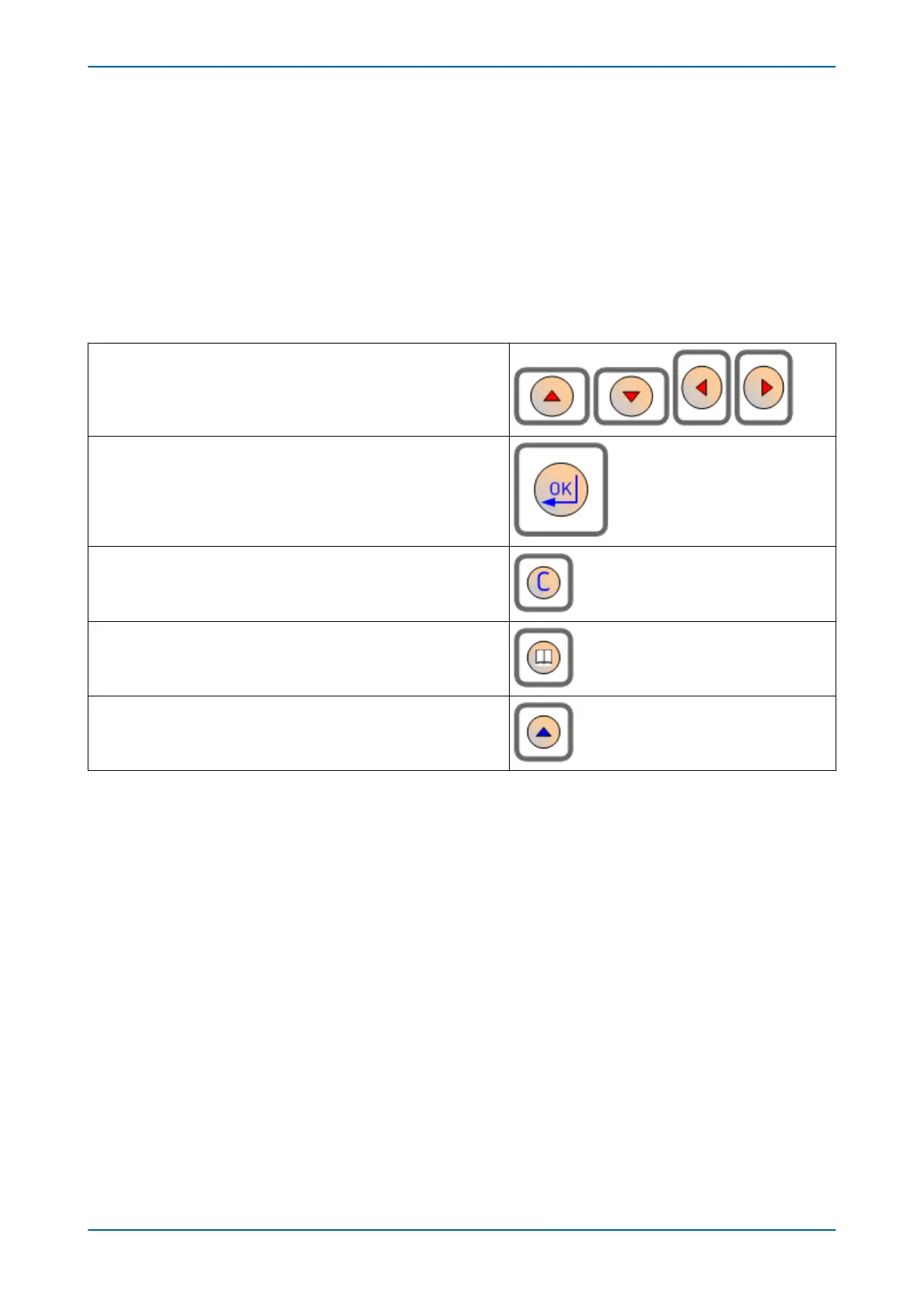
4.1.2 KEYPAD
The keypad consists of the following keys:
4 arrow keys to navigate the menus (organised around the Enter key)
An enter key for executing the chosen option
A clear key for clearing the last command
A read key for viewing larger blocks of text (arrow keys now used for
scrolling)
2 hot keys for scrolling through the default display and for control of
setting groups. These are situated directly below the LCD display.
4.1.2.1 LIQUID CRYSTAL DISPLAY
The LCD is a high resolution monochrome display with 16 characters by 3 lines and controllable back light.
4.1.3
FRONT SERIAL PORT (SK1)
The front serial port is a 9-pin female D-type connector, providing RS232 serial data communication. It is situated
under the bottom hinged cover, and is used to communicate with a locally connected PC. It is used to transfer
settings data between the PC and the IED.
The port is intended for temporary connection during testing, installation and commissioning. It is not intended to
be used for permanent SCADA communications. This port supports the Courier communication protocol only.
Courier is a proprietary communication protocol to allow communication with a range of protection equipment,
and between the device and the Windows-based support software package.
This port can be considered as a DCE (Data Communication Equipment) port, so you can connect this port device
to a PC with an EIA(RS)232 serial cable up to 15 m in length.
The inactivity timer for the front port is set to 15 minutes. This controls how long the unit maintains its level of
password access on the front port. If no messages are received on the front port for 15 minutes, any password
access level that has been enabled is cancelled.
Chapter 3 - Hardware Design P446SV
36 P446SV-TM-EN-1
 Loading...


