5.4 APPLICATION NOTES
5.4.1 INSULATED SYSTEMS
When insulated systems are used, it is not possible to detect faults using standard earth fault protection. It is
possible to use a residual overvoltage device to achieve this, but even with this method full discrimination is not
possible. Fully discriminative earth fault protection on this type of system can only be achieved by using a SEF
(Sensitive Earth Fault) element. This type of protection detects the resultant imbalance in the system charging
currents that occurs under earth fault conditions. A core balanced CT must be used for this application. This
eliminates the possibility of spill current that may arise from slight mismatches between residually connected line
CTs. It also enables a much lower CT ratio to be applied, thereby allowing the required protection sensitivity to be
more easily achieved.
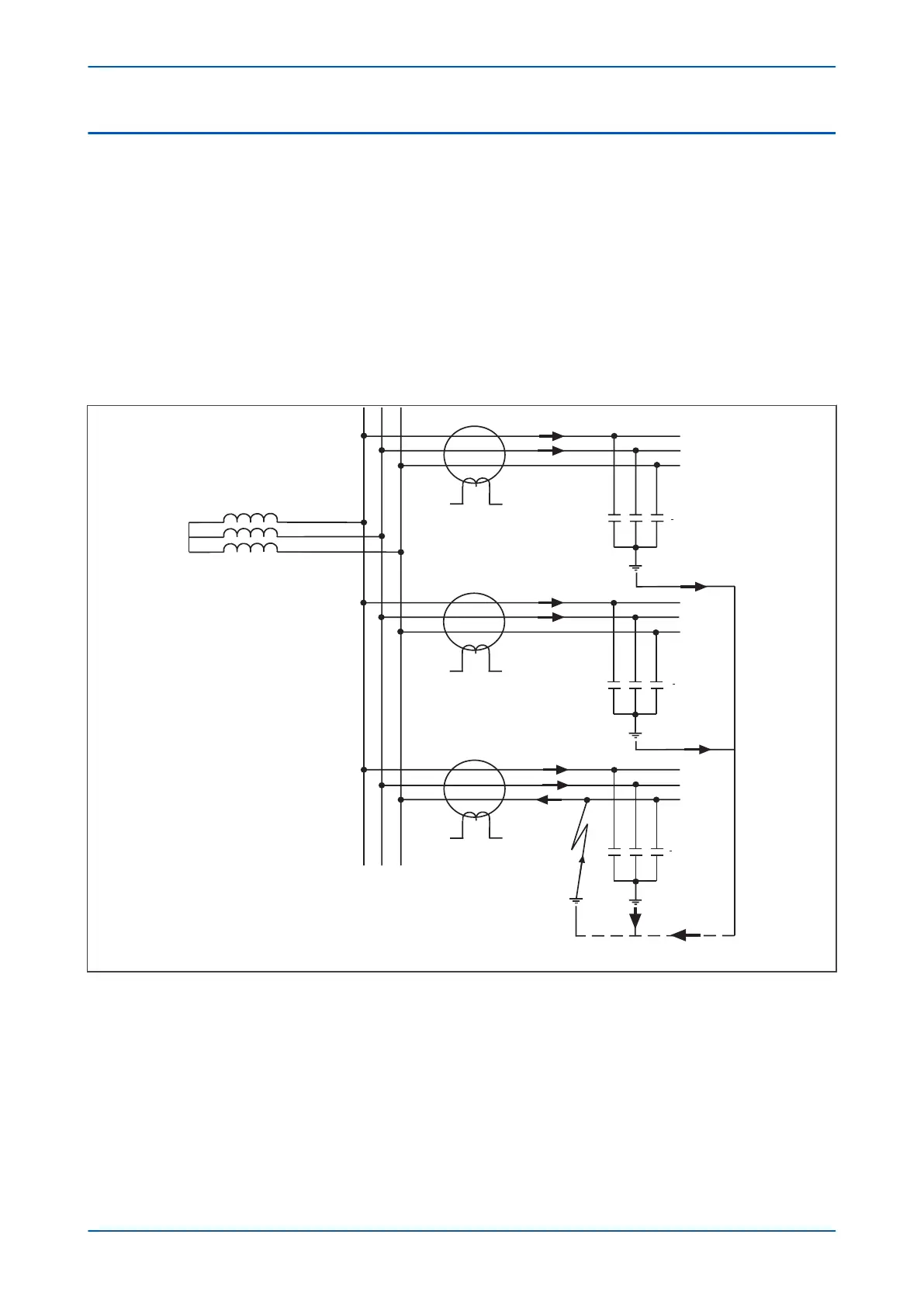
The following diagram shows an insulated system with a C-phase fault.
E00627
IR3
IR3 = IH1 + IH2 + IH3 - IH3
IR3 = IH1 + IH2
IH3
IH1 + IH2
IH1 + IH2 + IH3
jXc3
Ia3
Ib3
IH2
jXc2
IR2
Ia2
Ib2
IH1
jXc1
IR1
Ia1
Ib1
Figure 208: Current distribution in an insulated system with C phase fault
The protection elements on the healthy feeder see the charging current imbalance for their own feeder. The
protection element on the faulted feeder, however, sees the charging current from the rest of the system (IH1 and
IH2 in this case). Its own feeder's charging current (IH3) is cancelled out.
With reference to the associated vector diagram, it can be seen that the C-phase to earth fault causes the
voltages on the healthy phases to rise by a factor of √3. The A-phase charging current (Ia1), leads the resultant A
phase voltage by 90°. Likewise, the B-phase charging current leads the resultant Vb by 90°.
P446SV Chapter 13 - Current Protection Functions
P446SV-TM-EN-1 373
 Loading...


