V02775
jX
-jX
R-R
-10°
20%
Power Swing region
(shaded area)
Blind Region
Zone x
Operate Region
Blind Region
Load blinder boundary
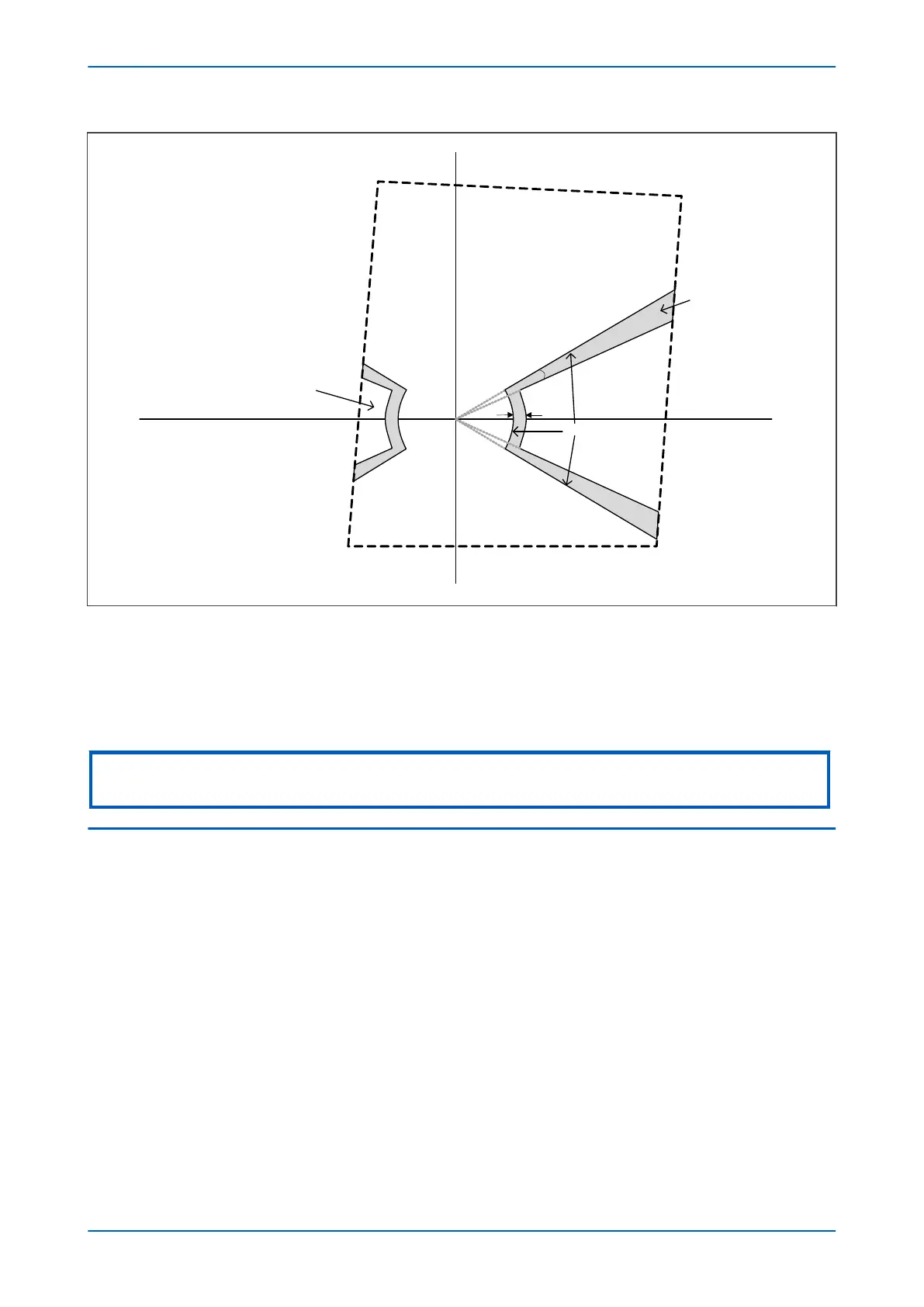
Figure 122: Load Blinder Boundary Conditions
The area is defined by lines created with angles fixed at 10° closer to the resistive axis than those created by the
load blinder angle setting (Load/B Angle - 10°) and a circular arc with a radius concentric with, and equivalent
to 20% greater than, the load blinder impedance setting (Z< Blinder Imp + 20%).
This is clearly indicated with reference to the diagram.
Note:
This power swing conditions are completely independent of the slow swing associated with Zone 7 and Zone 8.
3.5
POWER SWING BLOCKING LOGIC
The Power Swing function follows the logic diagram below:
Chapter 10 - Power Swing Functions P446SV
236 P446SV-TM-EN-1
 Loading...


