6 BOARDS AND MODULES
Each product comprises a selection of PCBs (Printed Circuit Boards) and subassemblies, depending on the chosen
configuration.
6.1 PCBS
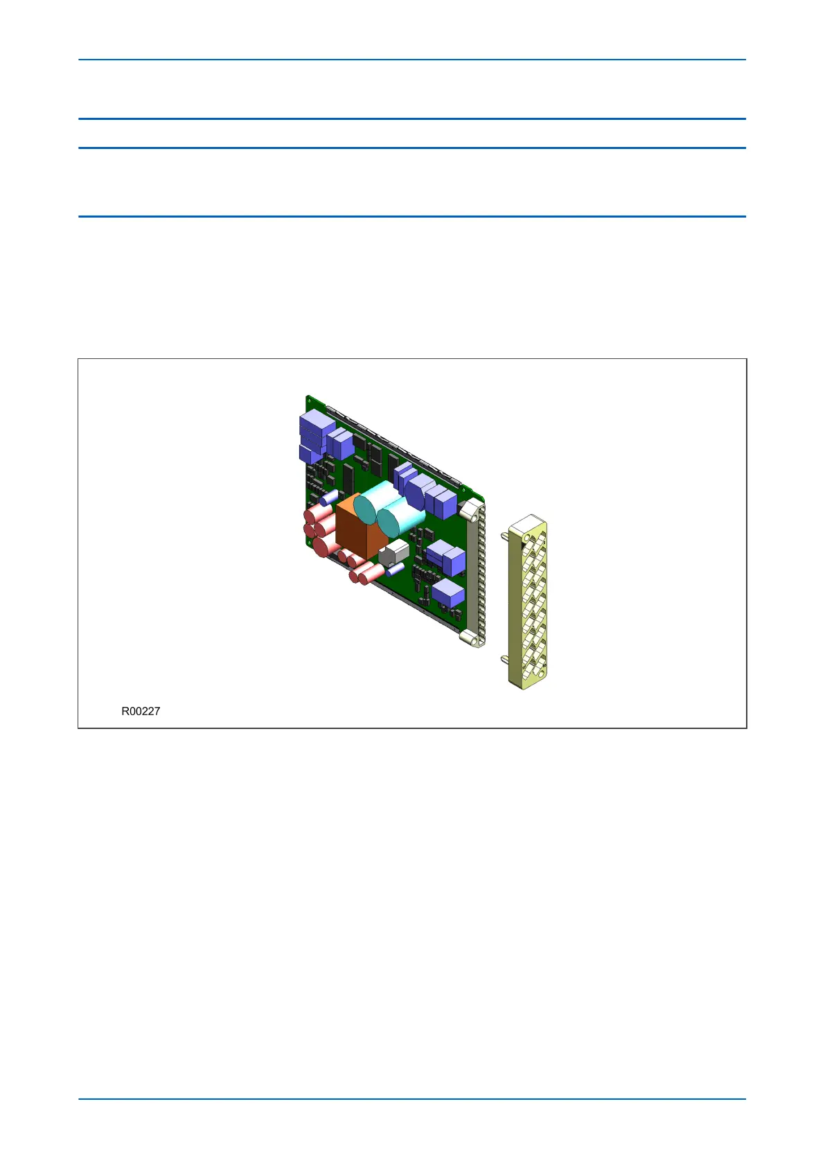
A PCB typically consists of the components, a front connector for connecting into the main system parallel bus via
a ribbon cable, and an interface to the rear. This rear interface may be:
● Directly presented to the outside world (as is the case for communication boards such as Ethernet Boards)
● Presented to a connector, which in turn connects into a terminal block bolted onto the rear of the case (as is
the case for most of the other board types)
Figure 8: Rear connection to terminal block
P446SV Chapter 3 - Hardware Design
P446SV-TM-EN-1 39
 Loading...


