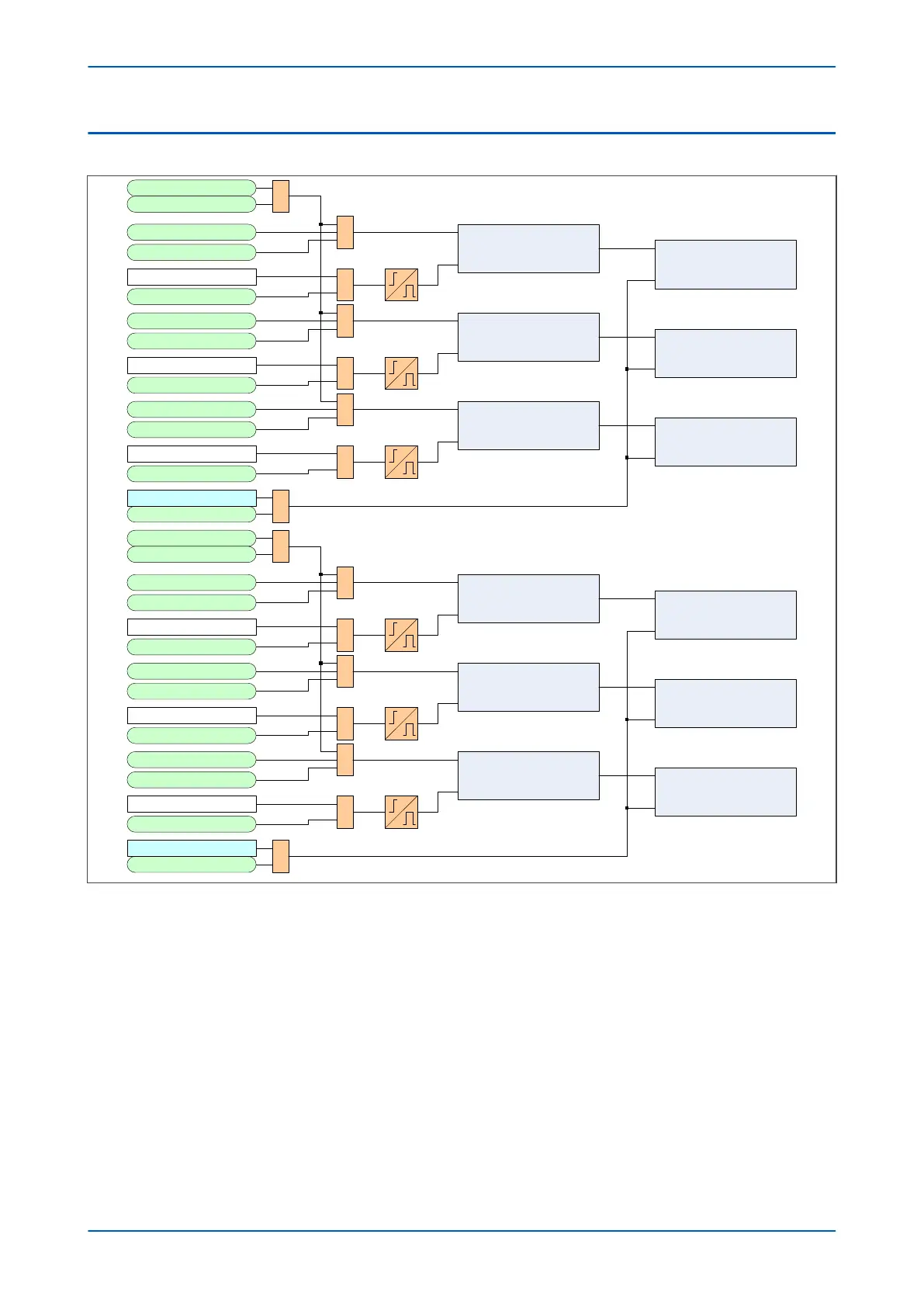
V01275
CB1 operating time phase A
Start
Stop
CB1 Trip 3ph
1
CB1 Ext Trip3ph
CB1 Trip OutputA
CB1 Ext Trip A
CB1 Trip OutputB 1
CB1 Ext Trip B
Note: CB operating time not accumulated when device is in test mode
Pole Dead A
CB1 operating time phase B
Start
Stop
1
1
Pole Dead B
1
CB1 Trip OutputC 1
CB1 Ext Trip C
CB1 operating time phase C
Start
Stop
Pole Dead C
1
1
Rst CB1 Data
Reset CB1 Data
CB1OpTimePhA Counter
Increment
Reset
CB1OpTimePhB Counter
Increment
Reset
CB1OpTimePhC Counter
Increment
Reset
IA < fixed threshold
IB < fixed threshold
IC < fixed threshold
CB2 operating time phase A
Start
Stop
CB2 Trip 3ph
1
CB2 Ext Trip3ph
CB2 Trip OutputA
CB2 Ext Trip A
CB2 Trip OutputB 1
CB2 Ext Trip B
Pole Dead A
CB2 operating time phase B
Start
Stop
1
1
Pole Dead B
1
CB2 Trip OutputC 1
CB2 Ext Trip C
CB2 operating time phase C
Start
Stop
Pole Dead C
1
1
Rst CB2 Data
Reset CB2 Data
CB2OpTimePhA Counter
Increment
Reset
CB2OpTimePhB Counter
Increment
Reset
CB2OpTimePhC Counter
Increment
Reset
IA < fixed threshold
IB < fixed threshold
IC < fixed threshold
526
534
523
535
892
524
536
893
525
537
894
447
1600
538
1601
539
892
1602
540
893
1603
541
894
1597