V01273
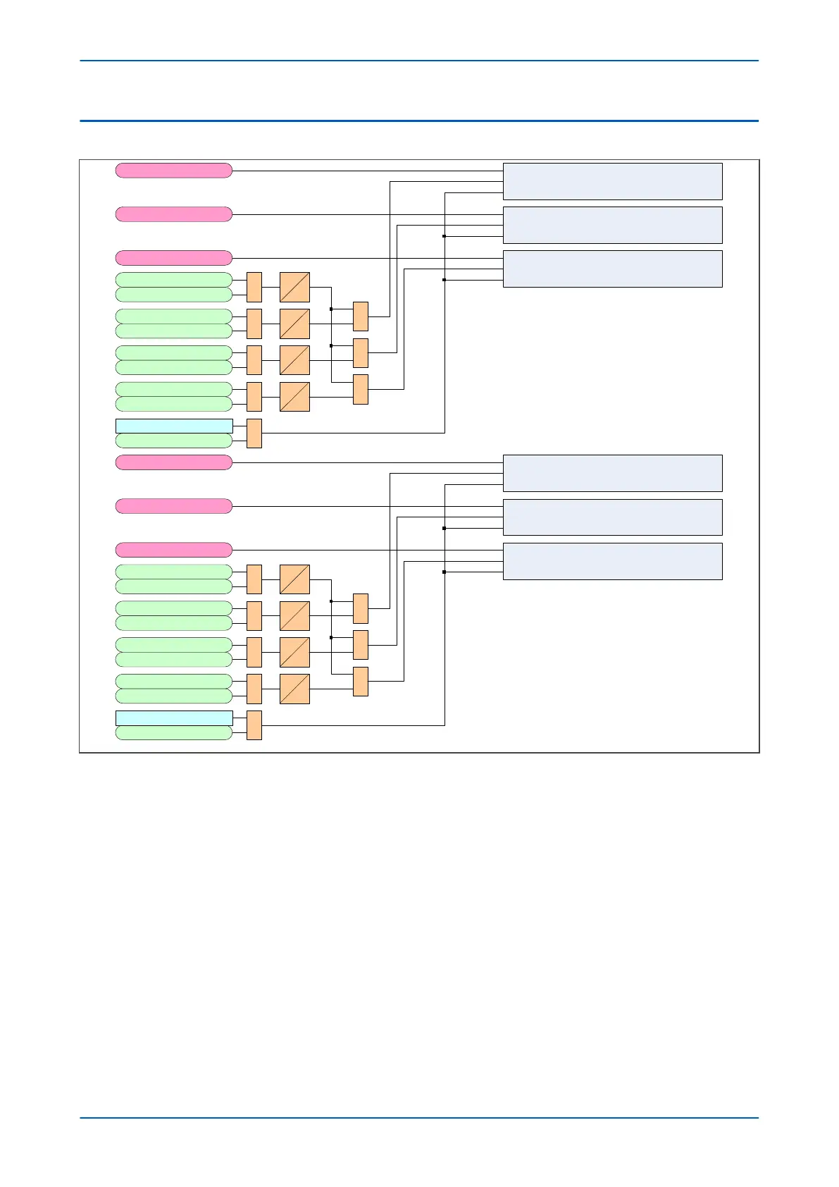
Set CB1 Cumulative IA broken InSet
Reset
CB1PhaseACurrent
Set CB1 Cumulative IB broken InSet
Reset
CB1PhaseBCurrent
Set CB 1 Cumulative IC broken InSet
Reset
CB1PhaseCCurrent
CB1 Trip 3ph
1
CB1 Ext Trip3ph 0
t
CB1 Trip OutputA
1
CB1 Ext Trip A
0
t
CB1 Trip OutputB
1
CB1 Ext Trip B 0
t
CB1 Trip OutputC
1
CB1 Ext Trip C 0
t
1
1
1
1
Reset CB Data
Reset CB Data
Note: Broken current totals not incremented when device is in test mode
Set CB2 Cumulative IA broken InSet
Reset
CB2PhaseACurrent
Set CB2 Cumulative IB broken InSet
Reset
CB2PhaseBCurrent
Set CB 2 Cumulative IC broken InSet
Reset
CB2PhaseCCurrent
CB2 Trip 3ph
1
CB2 Ext Trip3ph 0
t
CB2 Trip OutputA
1
CB2 Ext Trip A 0
t
CB2 Trip OutputB
1
CB2 Ext Trip B
0
t
CB2 Trip OutputC
1
CB2 Ext Trip C
0
t
1
1
1
1
Reset CB Data
Reset CB Data
Note: Broken current totals not incremented when device is in test mode
Note: All timers have 1 cycle pickup delay
526
534
523
535
524
536
525
537
447
1600
538
1601
539
1602
540
1603
541
447
 Loading...


