RJ45 Connector
This is a service port for commissioning and testing only. Do not use this for permanent connections.
LEDs
LED Function On Off Flashing
Green Link Link ok Link broken
Yellow Activity Traffic
Note:
The 9-2LE interface fibre port does not support auto negotiation. Ensure the Ethernet port of the device connected to the 9-2
LE interface fibre port is set to 100Mbps full duplex.
6.5
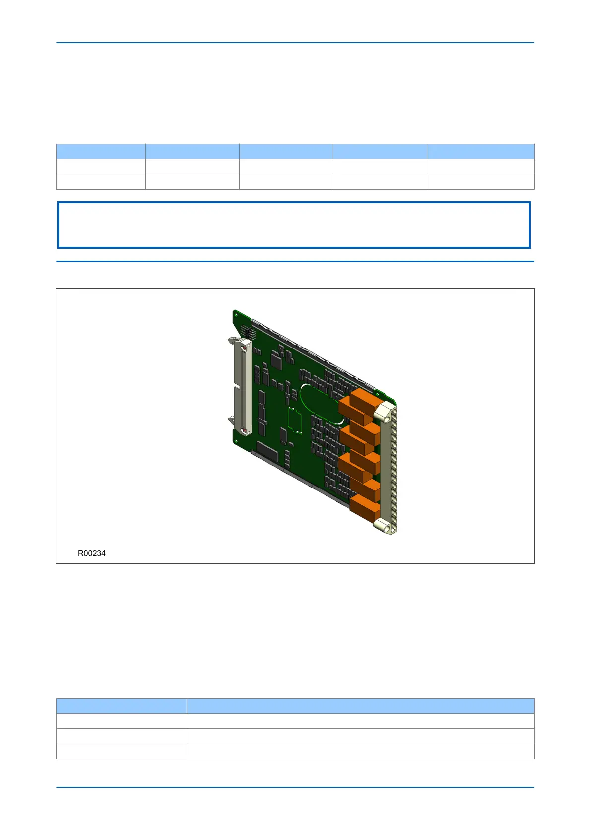
STANDARD OUTPUT RELAY BOARD
Figure 16: Standard output relay board - 8 contacts
This output relay board has 8 relays with 6 Normally Open contacts and 2 Changeover contacts.
The output relay board is provided together with the power supply board as a complete assembly, or
independently for the purposes of relay output expansion.
There are two cut-out locations in the board. These can be removed to allow power supply components to
protrude when coupling the output relay board to the power supply board. If the output relay board is to be used
independently, these cut-out locations remain intact.
The terminal numbers are as follows:
Terminal Number
Output Relay
Terminal 1 Relay 1 NO
Terminal 2 Relay 1 NO
Terminal 3 Relay 2 NO
Chapter 3 - Hardware Design P446SV
46 P446SV-TM-EN-1
 Loading...


