Terminal Number Output Relay
Terminal 4 Relay 2 NO
Terminal 5 Relay 3 NO
Terminal 6 Relay 3 NO
Terminal 7 Relay 4 NO
Terminal 8 Relay 4 NO
Terminal 9 Relay 5 NO
Terminal 10 Relay 5 NO
Terminal 11 Relay 6 NO
Terminal 12 Relay 6 NO
Terminal 13 Relay 7 changeover
Terminal 14 Relay 7 changeover
Terminal 15 Relay 7 common
Terminal 16 Relay 8 changeover
Terminal 17 Relay 8 changeover
Terminal 18 Relay 8 common
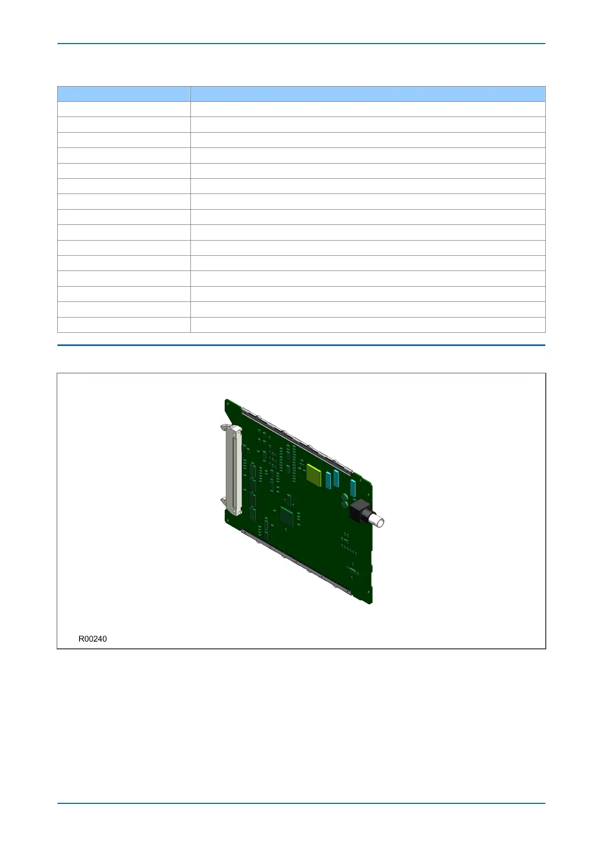
6.6 IRIG-B BOARD
Figure 17: IRIG-B board
The IRIG-B board can be fitted to provide an accurate timing reference for the device. The IRIG-B signal is
connected to the board via a BNC connector. The timing information is used to synchronise the IED's internal real-
time clock to an accuracy of 1 ms. The internal clock is then used for time tagging events, fault, maintenance and
disturbance records.
IRIG-B interface is available in modulated or demodulated formats.
P446SV Chapter 3 - Hardware Design
P446SV-TM-EN-1 47
 Loading...


