Appendix E. CE Mark Compliance
94 XMTC User’s Manual
E.2 EMI Filter Board
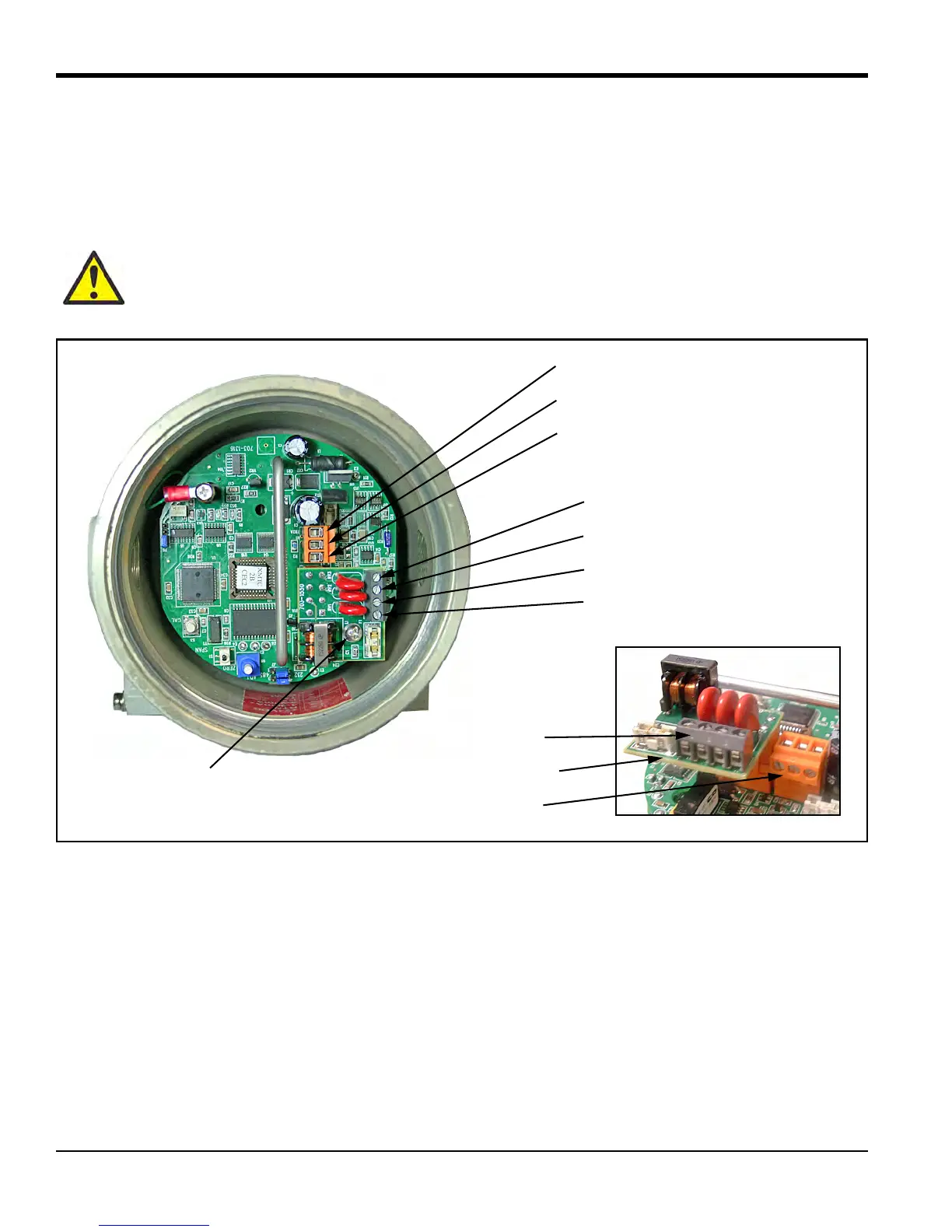
For CE compliance, an EMI filter board has been added to the XMTC (see Figure 88 below). This board is connected
internally to terminal block
TB1. The power and analog output connections are now made to terminal block TB3 on the
EMI filter board. The RS232 digital output connections are made to terminal block
TB2.
Figure 88: XMTC with EMI Filter Board - Wiring Connections
CAUTION! Do not make any connections to unassigned or unused terminals.
TB2-3 = RS232 GND (green)
TB2-2 = RS232 TX (white)
TB2-1 = RS232 RX (red)
TB3-3 = +4 to 20 mA (white)
TB3-2 = 24VDC Return (black)
TB3-1 = +24VDC Line (red)
TB3-4 = -4 to 20 mA (green)
EMI Filter Board Mounting Screw
EMI Filter Board
TB2 Side View
TB3 Side View

 Loading...