Chapter 4. Calibration
46 XMTC User’s Manual
4.4 Preparing the Transmitter for Calibration (cont.)
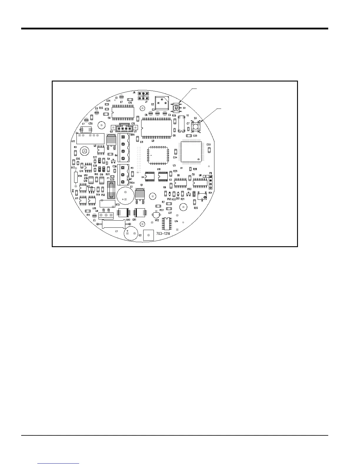
3. The XMTC printed circuit board (PCB) is located directly below the cover. Locate the switches S1 (zero and
span adjustment) and S3 (calibration button) using Figure 54 below as a guide.
Figure 54: Calibration Switch Locations
4.5 2-Port (Sealed Reference Gas) Calibration
1. Connect the XMTC Sample Inlet to the zero gas via the Zero Gas Inlet on the sample system or other gas
control system.
2. Establish a flow rate of 0.5 SCFH (250 cc/min) of zero gas at 0.0 psig to the XMTC.
3. Allow 2-5 minutes for the reading to settle. Move S1 to the zero position (marked on the PCB). Press S3 (the
calibration button) for about 20 seconds.
4. Connect the XMTC Sample Inlet to the span gas via the Span Gas Inlet on the sample system or other gas
control system.
5. Establish a flow rate of 0.5 SCFH (250 cc/min) of span gas at 0.0 psig to the XMTC.
6. Allow 2-5 minutes for the reading to settle. Move S1 to the span position (marked on the PCB). Press S3 (the
calibration button) for about 20 seconds.
Cal Button (S3)
Zero and Span Adjustment (S1)

 Loading...