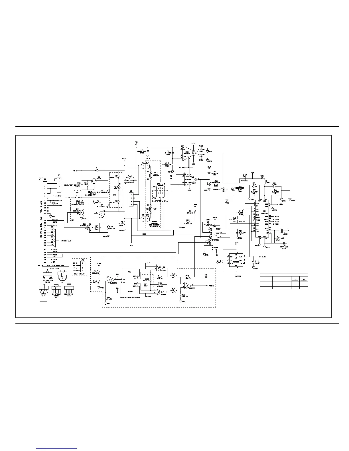
EasyManuals Logo
Home>GE>Transmitter>XMTC

GE XMTC User Manual

GE XMTC
126 pages
To Next Page IconTo Next Page
To Previous Page IconTo Previous Page
Page #84 background imageLoading...
Page #84 background image
Appendix C. Installation and Wiring Diagrams
XMTC User’s Manual 74
TABLE 3
GROUPS
NUMBER
DESCRIPTION R6 R7
-02 TC 7680 2260
-03 OX 6340 3650
-04 OX + PRESS 6340 3650
-01 STANDARD
PRESSURE COMPENSATION OX + PRESS
NOTES:
1. RESISTORS VALUES ARE OHMS, 5%, 1/4W UNLESS SHOWN OTHERWISE
2. SMD RESISTORS VALUES ARE OHMS, 5%, 1/8W UNLESS SHOWN OTHERWISE.
3. CAPACITORS VALUES ARE MICROFARADS UNLESS SHOWN OTHERWISE.
4. [ ] DENOTES SMD MARKING CODES.
5. IC POWER, LAST USED, AND DECOUPLING CAPACITORS SHOWN ON PAGE 2.
Figure 63: Analog PCB Schematic (ref. 700-1276, Rev. F, SH1)

Table of Contents

Questions and Answers:

Question and Answer IconNeed help?

Do you have a question about the GE XMTC and is the answer not in the manual?

GE XMTC Specifications

General IconGeneral
BrandGE
ModelXMTC
CategoryTransmitter
LanguageEnglish

Related product manuals