XMTC User’s Manual 65
Appendix B. Typical Applications
B.2.2 Equipment (cont.)
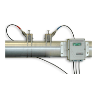
The sample system consists of inlet needle valves for sample, zero, span, and reference gases; a 4-port explosion-proof
XMTC; two pressure gauges; and two flowmeters. All components are mounted on a painted steel plate. A pump may
be needed to draw a sample through the sample system.
Note: A TMO2D or XDP display package is typically used. A GE moisture analyzer display package can be used
when the H
2
measurement is to be made in conjunction with a moisture measurement.
B.2.3 Basic Operating Procedure
The H
2
purity is continuously monitored at the generator. A sample gas flow of 0.5 SCFH (250 cc/min) is established.
A hydrogen reference gas flow of 0.4 SCFH (200 cc/min) is sufficient for proper operation. The sample system should
be located in an area cooler than 50
o
C (122
o
F), and the tubing leading to the sample system should be at least 5 ft
(1.5 m) long to insure proper cooling of the sample gas.
For this application the required calibration gases are as follows:
• Zero gas - 80.0% H
2
in N
2
• Span gas - H
2
(minimum 99.95 % purity)
• Reference gas - same as span gas
A typical XMTC Calibration Data Sheet is shown in Figure 59 below.
Figure 59: Typical XMTC Calibration Data Sheet
XM TC CALIB RATION S HEE T
T HE RMAL CONDUCTIVITY TRANSM ITT ER
XMTC Transmi tter
Serial Number TC-135
Part Number XMTC-42-1
Range, % 80 to 100% H
2
in N
2
Output 4 to 20 mA
PC Board 703-1095
Work Order: PCI 94445
Calibration Date: September 1, 2000
Point %H
2
* H
2
, mA
1 80.00 4.00
2 90.00 11.62
3 100.00 20.00
*Calibration is with Hydrogen (H
2
) in Nitrogen (N
2
)

 Loading...