Chapter 2. Installation
14 XMTC User’s Manual
2.4.3 Cable Specifications (cont.)
Table 3 below shows the connections for the GE standard 3-wire RS232 cable (P/N 704-668), which is available with a
male or female DB-9 or a DB-25 connector. This cable is available in standard lengths of 6 ft (2 m) and 12 ft (4 m).
Note: See EIA-RS Serial Communications (document 916-054) for detailed RS232 wiring instructions.
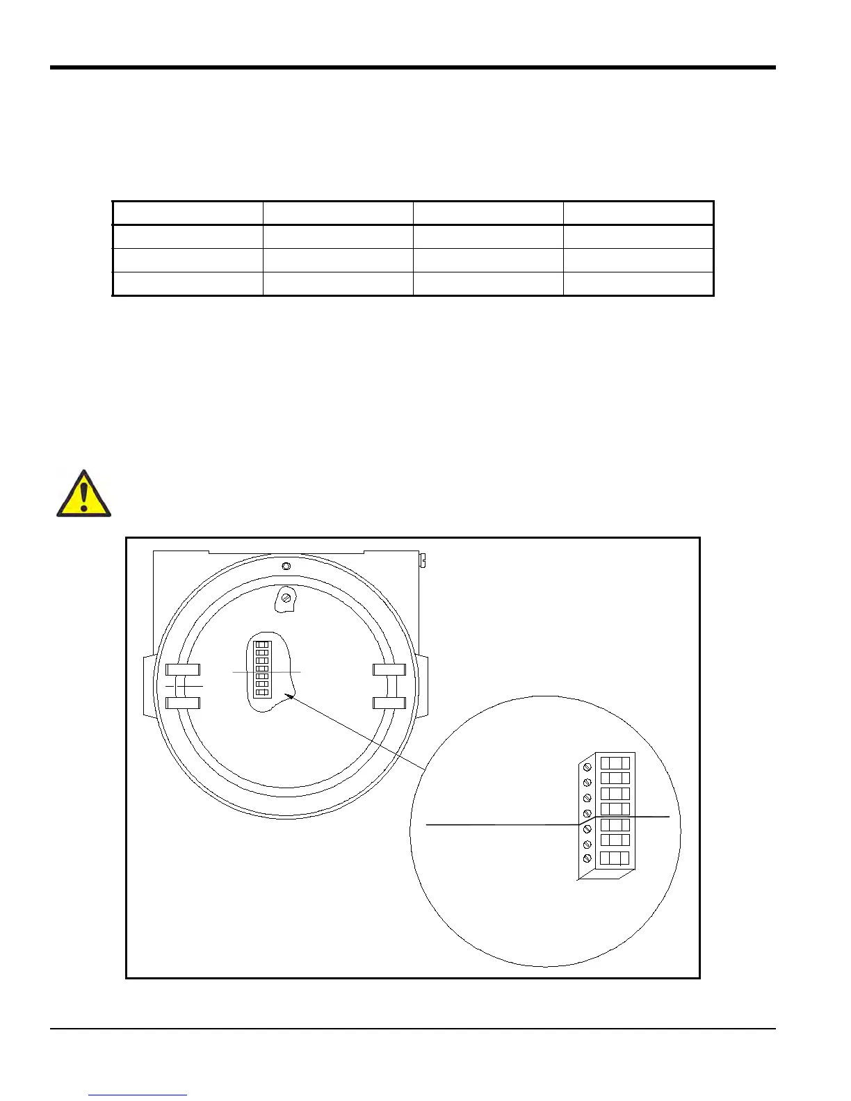
2.4.4 Wiring the Signal Connections
The XMTC power input, analog output, and RS232 connections are made to terminal blocks TB1 and TB2, which are
accessed by removing the XMTC cover. See Figure 7 below for the location and pin designations for terminal blocks
TB1 and TB2. Also refer to Appendix C, Installation and Wiring Diagrams.
Figure 7: XMTC Signal Wiring Connections
Table 3: GE 3-Wire RS232 Cable
Lead Color AWG Terminal
RX Red 22 TB2-1
TX White 22 TB2-2
GND Green 22 TB2-3
CAUTION! Do not make any connections to unassigned or unused terminals.
TB1
TB2
SIGNAL CONNECTIONS
1
2
3
4
1
2
3
+24VDC Line (red) 1
24VDC Return (black) 2
+4 to 20 mA (white) 3
–4 to 20 mA (green) 4
RS232 RX (red) 1
RS232 TX (white) 2
RS232 GND (green) 3

 Loading...