XMTC User’s Manual 95
Appendix E. CE Mark Compliance
E.3 Wiring the Signal Connections for the Weatherproof Version
Refer to Figure 88 on page 94, and complete the following steps to make the proper wiring connections:
1. Install the first cable entry device in accordance with the manufacturer’s instructions.
Note: If installation of the cable entry device is only partially complete, GE recommends tagging the device to ensure
the safety of subsequent users.
a. Thread the cable gland entry body into the XMTC port closest to the terminal blocks.
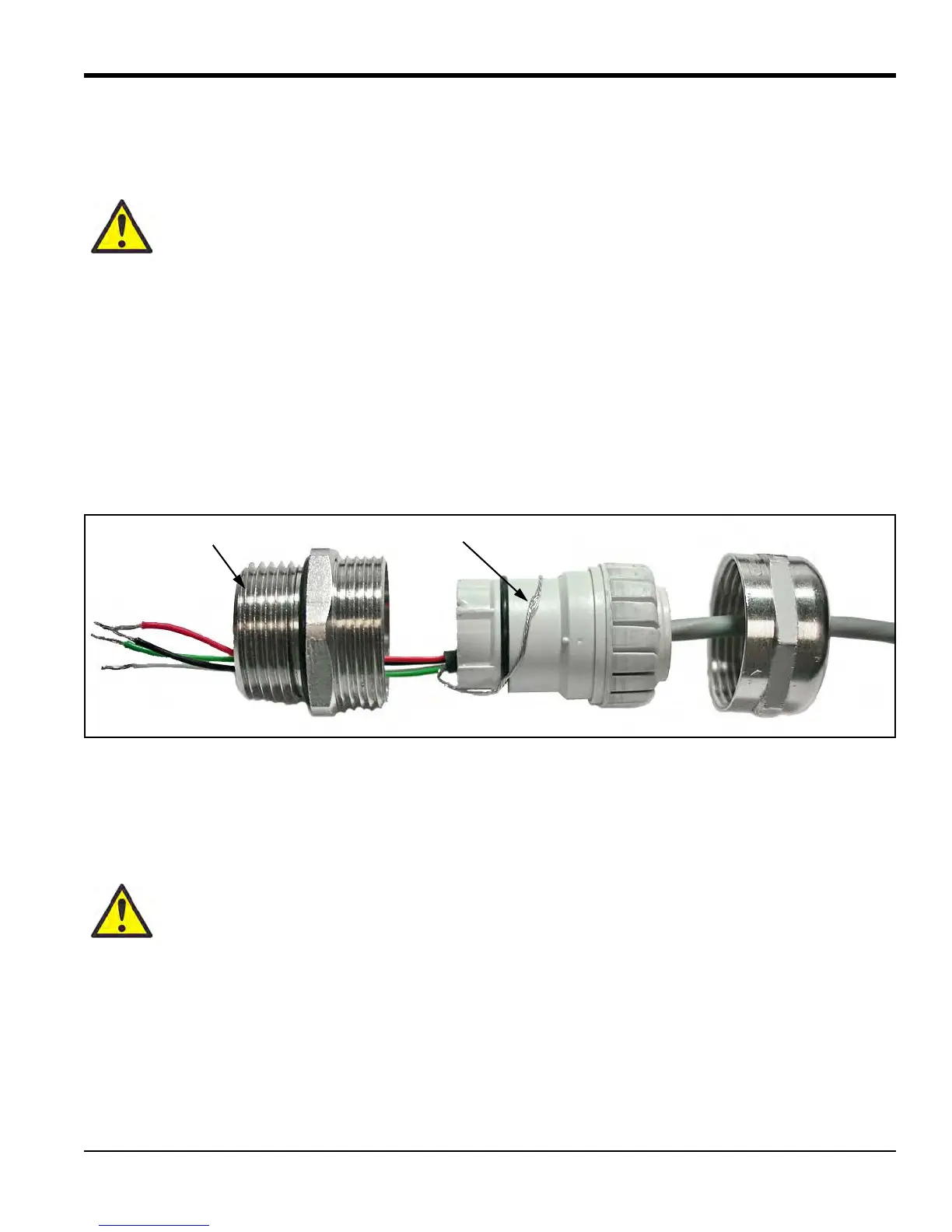
b. Route the 4-wire power/analog output cable through the cable gland as shown in Figure 89 below.
c. After terminating the shield as shown, assemble the three gland pieces together and tighten the gland to
secure the cable and the shield.
IMPORTANT: The cable shield must be terminated in the cable gland as shown in Figure 89 below.
Figure 89: Proper Cable Gland Assembly (GE p/n 419-215)
2. Remove the screw that secures the EMI filter board to its standoff. Then, pull the board from its socket to
access the TB3 connector, and loosen the terminal screws on the TB3 connector.
3. Connect the power leads:
a. Insert the 4-wire cable +24 VDC line (red) lead into pin TB3-1 and tighten the screw.
b. Insert the 4-wire cable 24 VDC return (black) lead into pin TB3-2 and tighten the screw.
4. Connect the analog output leads:
a. Insert the 4-wire cable + 4-20 mA (white) lead into pin TB3-3 and tighten the screw.
b. Insert the 4-wire cable – 4-20 mA (green) lead into pin TB3-4 and tighten the screw.
WARNING! Cable entries of an approved flameproof design are required. These must be
installed according to the manufacturer’s instructions. The choice of cable entry device may limit
the overall installation category achieved.
CAUTION! Connecting the +24 VDC line (red) lead to any terminal except TB3-1 will damage
the XMTC.

 Loading...