Chapter 2. Installation
10 XMTC User’s Manual
2.3 Mounting the Sample System
You can order a complete sample system from the factory. This includes the XMTC transmitter and all necessary
components and sample tubing mounted on a metal panel. Several standard sample systems are available, and
custom-designed sample systems can be built to your exact specifications.
Mount the sample system as close to the process sample point as possible. Once the sample system is mounted, connect
all inlet and outlet lines via the 1/4” compression fittings on the sample system. The sample line leading from the
process to the sample system should be of 1/4” stainless steel tubing, and should be as short as possible in order to
ensure a representative sample.
Following are descriptions of two standard sample systems:
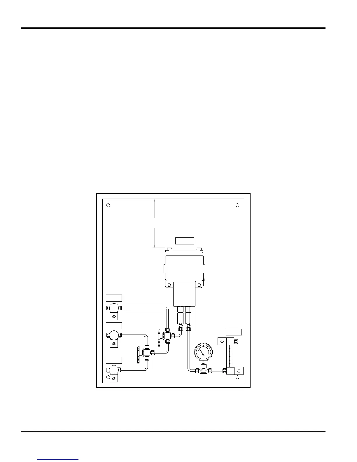
2.3.1 Manual, 2-Port (Sealed Reference Gas) Sample System
Figure 4 below shows a basic sample system for a 2-Port (sealed reference gas) XMTC. This sample system consists of
inlet needle valves for sample, zero, and span gases; a ball valve; a 2-port XMTC; a pressure gauge; and a flowmeter.
All components are mounted on a painted steel plate. Other components could be added for filtration (filter/coalescer),
pressure control (regulator), or flow control (pump).
Figure 4: Basic 2-Port Sample System (732-164)
SPAN GAS
INLET
9.00
(229.5)
(MIN)
TRANSMITTER
SAMPLE GAS
INLET
ZERO GAS
INLET
SAMPLE GAS
OUTLET

 Loading...