7-2
dummyheaddummyhead
GOVERNOR SYSTEM
GOVERNOR SYSTEM
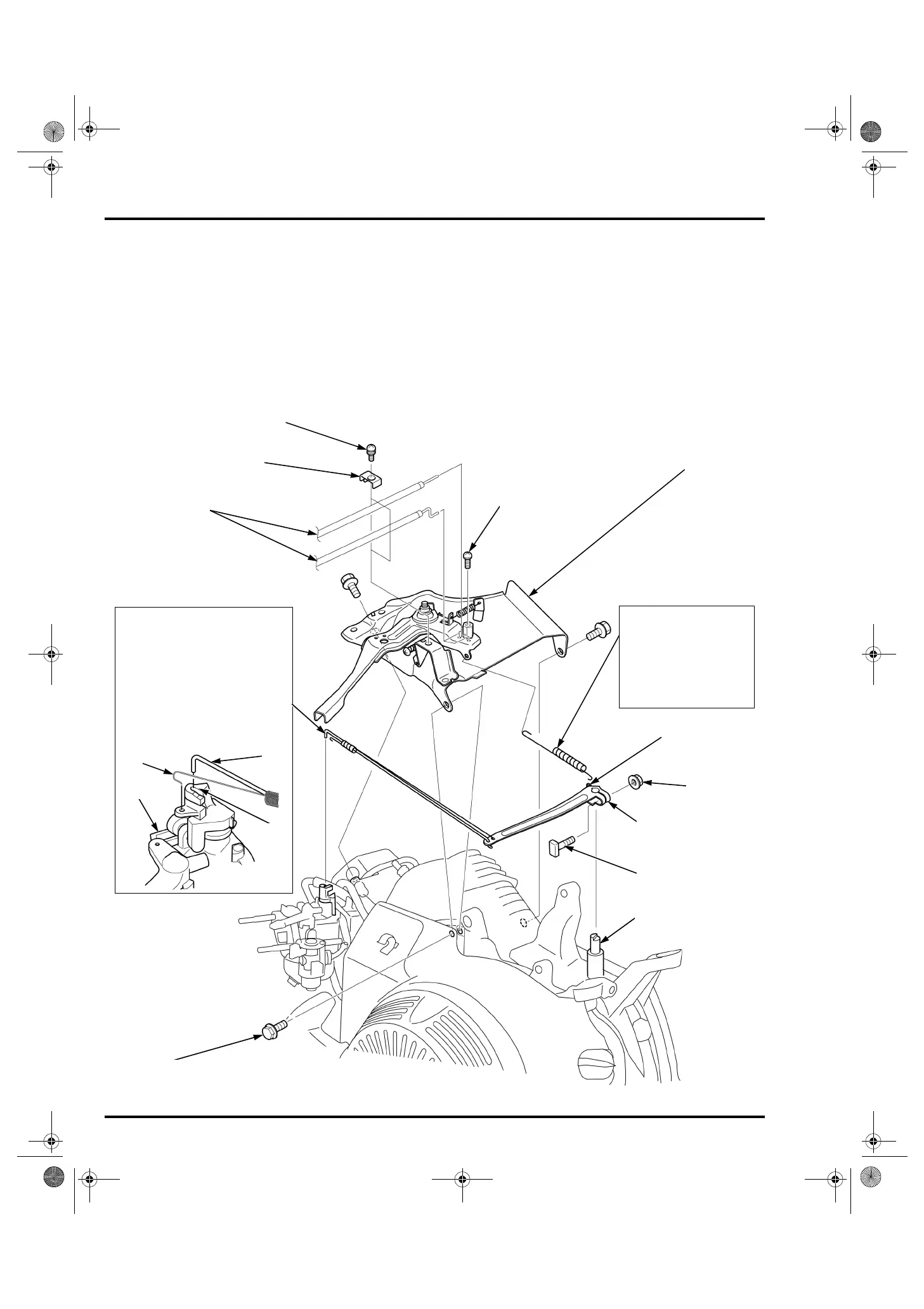
GOVERNOR ARM/CONTROL BASE
ASSY. REMOVAL/INSTALLATION
MANUAL OPERATION TYPE
Remove the following parts.
– Air cleaner (page 6-4)
– Muffler (page 12-2)
– Fuel tank (page 6-3)
– Tube clamp (page 6-9)
Installation is in the reverse of removal.
Adjust the maximum speed (page 7-8).
CONTROL BASE ASSY.
NUT (6 mm)
(If equipped)
(Commercially available)
GOVERNOR SPRING
SCREW (5 x 16 mm)
REMOVAL/INSTALLATION:
Pull the carburetor assy. [1]
toward to a point where the groove
[2] of the throttle arm lines up with
the governor rod [3], and then lift
the governor rod out of the hole of
the throttle arm and unhook the
throttle return spring [4].
GOVERNOR ROD/THROTTLE
RETURN SPRING
(If equipped)
(If equipped)
(If equipped)
OUTER HOLE
SCREW (4 x 6 mm)
INSTALLATION:
Install with the long end of
the spring toward the
control base assy.
Hook the governor spring
to the outer hole of the
governor arm.
GOVERNOR ARM
[3]
[4]
[1]
[2]
BOLT (6 x 12 mm) (3)
GOVERNOR ARM
SHAFT
GOVERNOR ARM
BOLT
CABLE HOLDER
REMOTE CABLE
62Z7B000.book 2 ページ 2012年9月27日 木曜日 午前10時21分
 Loading...