Wire detectors to zones Galaxy Flex Installer Manual
18
1. Terminate any unused zones inputs with a 1 kΩ resistor and program them as SPARE
(Menu 52.1.x.1=18).
2. If required, reprogram zone configurations and the resistance preset values using the
Zone Resistance menu (51 ent 46 ent).
3. If required, customise each zone to a specific preset using the Resistance Select menu
(52 ent 9 ent).
4. Limit the cable run on each zone to no more than 500 m. For presets 11 and 12, limit
the cable run to no more than 100 m.
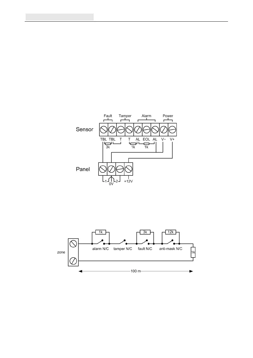
Detector connection
Wire detectors to zone terminals according to the following diagram:
Additional zone configuration information
Zones can be programmed with different resistance ranges or for normally-closed (N/C)
loops for zone status activation (see Zone Resistance [51.46] and Appendix H).
If a detector has separate fault and mask indications use the wiring shown in Figure 4.
Figure 4 Option 12 - Double balanced 1k fault/mask monitoring wiring
When this wiring mode is used, ensure only one detector is set to report fault conditions, and
l
imit the number of detectors or contacts of any type to a maximum of 2.
Note: The recommended maximum cable run from a zone to a detector is 500 metres in all
other configurations.
In end-of-line mode use the wiring shown in Figure 5.

 Loading...