System architecture Galaxy Flex Installer Manual
10
System architecture
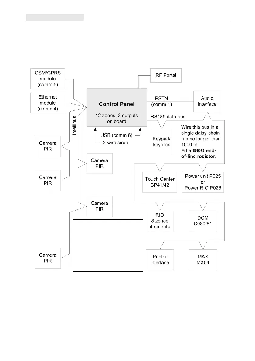
Figure 2 shows the full range of peripheral devices that can be connected to the system via
the RS485 data bus, the Intellibus, and other specific connection points on the control panel
PCB (see PCB layout and connections on page 12).
Figure 2 System configuration
Notes:
You can place the panel in the middle of an RS485 data bus chain. If you do this,
remove the 2-pin 680Ω line terminal link close to the battery connector (Figure 3)
and fit an EOL resistor to each end of the data bus.
When there are two or more Intellibus spurs that exceed 100 m, fit 120Ω EOL
resistors to the ends of the two longest spurs and remove the 120Ω line terminal link
close the Intellibus connector on the panel (Figure 3).
The Intellibus can have up to 4
cable runs from the panel. The
total length of all cables must
not exceed 400m, If only one
cable run is used the total length
can be up to 1000m. Set the
120 end-of-line resistor on the
last module on each of the two
longest spurs only

 Loading...