Galaxy Flex Installer Manual Appendix G: Peripherals
241
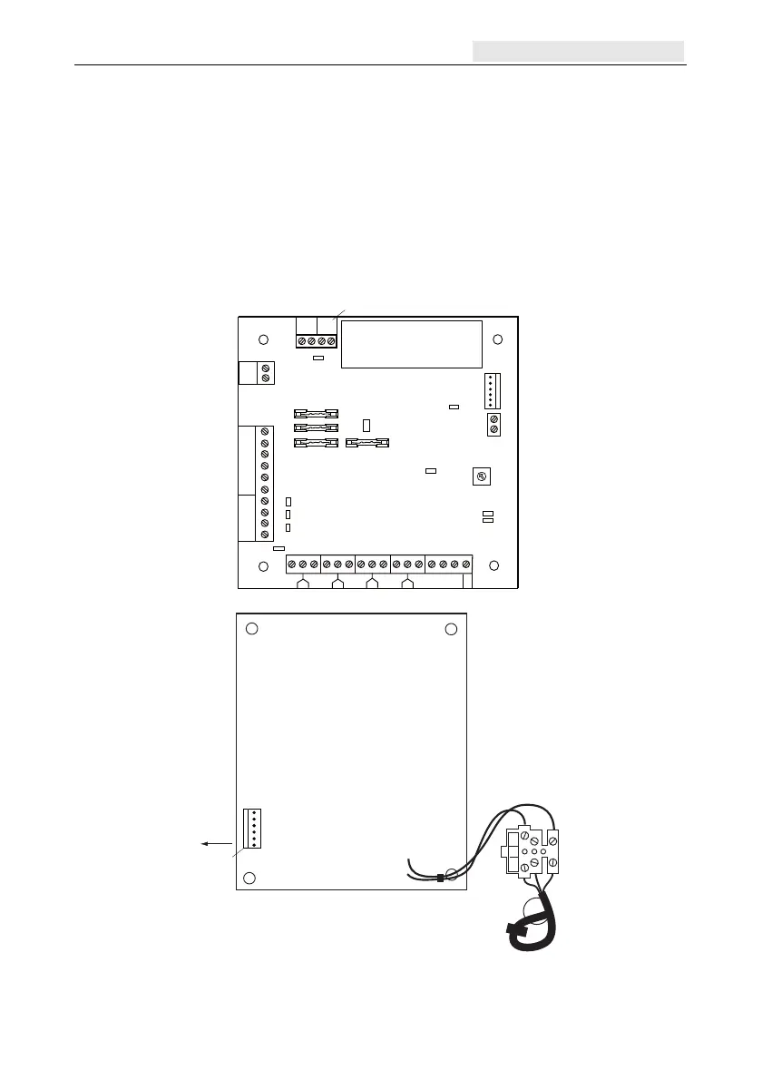
Power Supply Unit and Power RIO
The Power Supply Unit is available in 2 variants:
The Power RIO comprising power block and control unit with on-board RIO.
The Power Unit comprising power block and control unit only.
WARNING: There are lethal voltages present in the power block. Remove mains
power from the power block before handling it.
The number of Power Units or Power RIOs that can be used on a system is limited by the
number of RIOs that can be added to a panel.
1 1/2 2
3
3/4
4
5
5/6
6
7
7/8
8
zones 1 to 8
heatsink
COMs lines
outputs
rotary
address switch
AC
BAT
PWR
0 V
OP1
OP2
OP3
OP4
LID
TAM P
OW
TAM P
+14.5
0 V
+12 V1
A(DO
)
B(DI)
F1
F4
F3
F2
LK1
LK2
LK3
LK4
-BAT
+BAT
AC/F
BT
0 V
14.5
0 V
13.8
LED1
(COMs)
LED2
(AC)
Control Unit
+12 V2
0 V
0 V
FAU LT OP
external tamper
fr
om
Power Block
Bell box
connector
LK5
LK10
SLAVE
E/E
mains terminal block
power
header
to
Control
Unit
Power Block
NEUTRAL
LIVE
13.8V
0V
14.5V
0V
BT
AC
/F
WARNING: The Power Block PCB
is connected to mains voltage. Always
disconnect mains supply for at least
1 minute before removing the box lid.
Figure 14 Power supply unit

 Loading...