Galaxy Flex Installer Manual Install peripheral devices
25
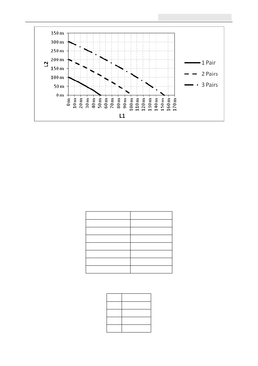
Figure 10 Power cable spans for two camera PIRs
L1 is the distance from the Power Supply to the first camera PIR
L
2 is the distance between the first and second camera PIR
Connection to the RS485 bus
Note: Do not connect cameras or an Ethernet module to this bus.
1. Before applying power, select a valid and unique address on each device. The address
on most devices is set by either jumpers or a rotary switch. Note that a Keyprox will
assume the address of both a keypad and a MAX reader. Care must be taken not to
duplicate addresses when a MAX reader and Keyprox are both installed
Peripheral Valid addresses
Mk8 Keypad 0-7
Mk8 Keyprox 0-7
TouchCenter 0-2
RIO/PSU 2-12
DCM Reader 0-3
MAX 0-7
RF Portal 0-15
2. Connect an RS485 data cable between the panel and each device in a daisy-chain
configuration, using the information in the tables below
Panel
Peripherals
+12 V
+ V in
0 V –
A A
B B

 Loading...